快速入门#
先备条件
在使用 geonodes 前,你必须先了解:
Blender几何节点Python语言如何在
blender中执行Python脚本
安装与你的 Blender 兼容的 geonodes 版本。
Important
您可以问自己实现特定节点的方法的名称是什么,以及节点套接字的名称是什么。只需使用名称的snake_case版本。有关详细信息,请参阅命名约定。您也可以参考API文档。
导入模块#
我们假设所有脚本都以以下导入指令开始:
import geonodes as gn
第一个节点树#
执行以下代码段:
import geonodes as gn

with gn.Tree("空树") as tree:

   # `og`和`ig`是`output_geometry`和`input_geometry`的缩写

   tree.og = tree.ig
这段代码只是创建了将输入几何图形连接到输出几何图形的树。
添加一个几何节点修改器到你的对象中,作为参数,在列表中选择名为空树的节点树。
但一切都不像预期的那样发生!
第一个节点操作#
让我们用输入几何面,来构造一些更有趣的东西。我们将细分它并使其平滑:
import geonodes as gn

with gn.Tree("Shading smooth") as tree:

  geo = gn.Mesh(tree.ig)      # 获取几何输入(a mesh)
                              # 初始化为一个`Mesh`对象,然后就能使用`Mesh`的方法

  geo.subdivide()             # 节点 'Subdivide Mesh'
  geo.set_shade_smooth(True)  # 节点 'Set Shade Smooth'

  tree.og = geo               # tree.output_geometry = geo 的缩写
域的使用#
Note
对几何图形的操作通常是对域属性的操作。通过明确操作哪个域,可以编写更清晰的代码。例如,给网格着色实际上是设置网格面属性。
更简明的写法:
geo.faces.shade_smooth = True
这一次,平滑的阴影被视为面(域)的属性。和其他属性一样,shade_smooth可以被设置,也可以被获取。
在下面的代码中,变量smoothed_faces包含了所有网格面的True或False值,这取决于它们是否被平滑。
smoothed_faces = geo.faces.shade_smooth
用户输入(Input)#
在几何节点中,用户参数被实现为树输入套接字。这些输入可以用所有geonodes类中可用的类构造函数Input来创建,例如:
import geonodes as gn

with gn.Tree("Geometry Nodes") as tree:
   object = gn.Object.Input(None, "Other geometry")
   count  = gn.Integer.Input(10, "Count", min_value=2)
   factor = gn.Float.Input(0.5, "Factor", min_value=0, max_value=1, description="Use this value to control the modifier effect")
   mat    = gn.Material.Input(None, "A material")
输入构造函数以套接字名作为参数。对于诸如Integer或Float之类的值,它将默认值作为第一个参数。它还可以接受min_value, max_value和描述参数,以便更好地控制。
节点树的输出(Output)#
如上所示,生成的几何图形可以输出:
tree.output_geometry = geo # 也可以使用别名缩写:tree.og
要输出其他值,使用所有类中可用的to_output方法:
v = mesh.verts.position   # Position of vertices
v.to_output("Location")   # Location output sockets is created. Its type is Vector
更进一步的例子#
让我们创建一个icosphere,添加两种材质,并在表面上随机设置材质。一旦完成,将挤压面与一个特定的材质。
再次之前,我们需要先知道:
创建几何体#
通过调用几何类的构造函数来创建几何图形。这些构造函数对应于Blender中“添加节点”菜单中的“基础网格”和“基础曲线”。
构造函数的名称构建为其节点名称的CamelCase版本。
icosphere = gn.Mesh.IcoSphere()
这将创建默认的icosphere。我们可能需要一些定制。查看节点引用Mesh.IcoSphere。
我们看到有两个参数:radius和subdivisions。它们被实现为构造函数的参数。
正如在命名约定中解释的那样,geonode使用snake_case版本的节点套接字和节点参数名称:
icosphere = gn.Mesh.IcoSphere(radius=1, subdivisions=3)
你可能想要对这些参数给予更多的控制:
radius    = gn.Float.Input(1, "Radius", min_value=0.01, max_value=10,\
            description="A reasonable radius for the sphere")
subs      = gn.Integer.Input(3, description="No limits: I trust you")
icosphere = gn.Mesh.IcoSphere(radius=radius, subdivisions=subs)
我们现在有了一个icosphere,它可以通过向用户公开参数来创建。
添加材质#
材质是面的特性。语法类似于mesh.faces.material = ...
材质用它的名称来实例化。让我们假设我们有两个名为“红色”和“蓝色”的现有材质。
为了将材质分配给我们的icosphere,我们写道:
icosphere.faces.material = "Red"
icosphere.faces.material = "Blue"
Warning
如果材质不存在,脚本就会崩溃。最好要求用户提供自己的材质:
mat_base = gn.Material.Input(None, "Base").    # Supposed to be Blue
mat_sel  = gn.Material.Input(None, "Selected") # Supposed to be Red

icosphere.faces.material = mat_base
icosphere.faces.material = mat_sel
域的选集#
产生的icosphere是红色的,因为第二个材质被分配给所有的面孔,覆盖了前一个分配。但我们想要的是随机选择不同颜色的面。可以通过使用选择参数“调用”它们来选择这些面。
icosphere.faces[ random_selection ].material = mat_sel
可以使用类Boolean的Random构造函数生成随机选择:
icosphere.faces[ gn.Boolean.Random(probability=0.5) ].material = mat_sel
这一次,红色材质将只覆盖50%的蓝色面。
另一种达到这个结果的方法是使用材质索引:
icosphere.faces.material = mat_base # --> Material index 1
icosphere.faces.material = mat_sel  # --> Material index 2
添加了两种材质,所有面的材质索引设置为2,让我们把它们的一半改回1:
icosphere.faces[ gn.Boolean.Random(probability=.5) ].material_index = 1
挤出#
Extrude Mesh节点接受一个域参数来定义必须挤出的内容。对于geonode,有3种可能性:
mesh.faces.extrude()
mesh.edges.extrude()
mesh.verts.extrude()
我们想要挤出面,但只是红色的面:
faces = icosphere.faces
faces[faces.material_index.equal(2)].extrude()
Note
使用material_index.equal(2)而不是material_index == 2。后一个表达式将给出一个 python bool结果,而不是预期的geonodes布尔值。
Note
后一种写法作为一种新特性在最新版中已经添加。2023-3-18
或者,如果你对材质索引没有信心,你可以使用material_selection方法:
faces[faces.material_selection(mat_sel)].extrude()
挤压本身可通过挤压参数进行控制:
faces[faces.material_index.equal(1)].extrude(offset_scale=0.3)
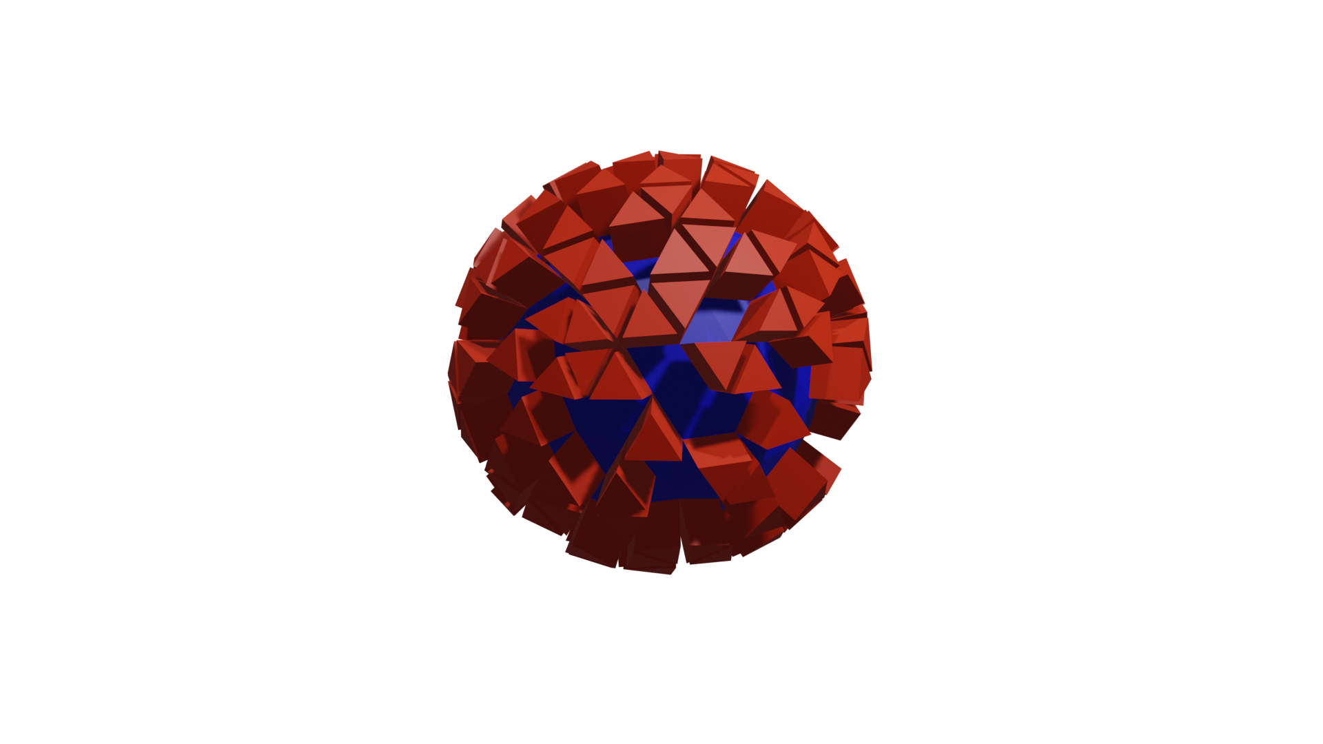
完整代码#
注意
头3行和尾7行用到了另外一个库,涉及对blender场景对象的操作,读者可以忽略。
from imare import *
init_modules(__file__, "imare", "geonodes")
flush_data()

import geonodes as gn

mat_a = bpy.data.materials.new("a")
mat_a.diffuse_color = (0, 0, 1, 1)

mat_b = bpy.data.materials.new("b")
mat_b.diffuse_color = (1, 0, 0, 1)

with gn.Tree("Geometry Nodes", reroute=False) as tree:

    # Good practice: let's start with the tree inputs

    radius = gn.Float.Input(1, "Radius", min_value=0.01, max_value=10,\
             description="A reasonable radius for the sphere")
    subs   = gn.Integer.Input(3, description="No limits: I trust you")

    mat_base = gn.Material.Input("a", "Base")
    mat_sel  = gn.Material.Input("b", "Selected")

    # The icosphere

    icosphere = gn.Mesh.IcoSphere(radius=radius, subdivisions=subs)

    # The materials

    faces = icosphere.faces

    faces.material = mat_base
    faces[gn.Boolean.Random(probability=.5)].material = mat_sel

    # Extrude the select faces

    faces[faces.material_index == 2].extrude(offset_scale=0.3)

    tree.og = icosphere


Tree({
    O.cube @ "Cube": {
        Mod.geometry_nodes: {
            "node_group": "Geometry Nodes",
        },
    },
}).load()