pynodes.geosocks#
Important
Geometry nodes in blender
Geometry nodes can modify different types of geometry:
Module Contents#
Classes#
Functions#
The Arc node generates a poly spline arc. The node has two modes, Radius and Points. |
|
The Arc node generates a poly spline arc. The node has two modes, Radius and Points. |
|
The Bézier Segment node generates a 2D Bézier spline from the given control points and handles. |
|
The Curve Circle node generates a poly spline circle. |
|
The Curve Circle node generates a poly spline circle. |
|
The Curve Line node generates poly spline line. |
|
The Curve Spiral node generates a poly spline in a spiral shape. It can be used to create springs or other similar objects. By default the spiral twists in a clockwise fashion. |
|
The Quadratic Bézier node generates a poly spline curve from the given control points. The generated shape is a parabola. |
|
The Quadrilateral node generates a polygon with four points, with different modes. |
|
The Quadrilateral node generates a polygon with four points, with different modes. |
|
The Quadrilateral node generates a polygon with four points, with different modes. |
|
The Quadrilateral node generates a polygon with four points, with different modes. |
|
The Quadrilateral node generates a polygon with four points, with different modes. |
|
The Star node generates a poly spline in a star pattern by connecting alternating points of two circles. The points on the inner circle are offset by a rotation so that they lie in between the points on the outer circle. This offset can be changed with the twist input. |
|
The Cone node generates a cone mesh that is optionally truncated. |
|
The Cube node generates a cuboid mesh with variable side lengths and subdivisions. The inside of the mesh is still hollow like a normal cube. |
|
The Cylinder node generates a cylinder mesh. It is similar to the Cone node but always uses the same radius for the circles at the top and bottom. |
|
The Grid node generates a planar mesh on the XY plane. |
|
The Icosphere node generates a spherical mesh that consists of equally sized triangles. |
|
The Mesh Circle node generates a circular ring of edges that is optionally filled with faces. |
|
The Mesh Circle node generates a circular ring of edges that is optionally filled with faces. |
|
The Mesh Circle node generates a circular ring of edges that is optionally filled with faces. |
|
The Mesh Line node generates vertices in a line and connects them with edges. |
|
The Mesh Line node generates vertices in a line and connects them with edges. |
|
The UV Sphere node generates a spherical mesh mostly out of quads except for triangles at the top and bottom. |
|
The Points node generate a point cloud with positions and radii defined by fields. |
|
The Volume Cube generates a volume from scratch by evaluating an input field on every single voxel in a rectangular prism. The Density field defines the output volume grid’s value at every voxel. The field can only depend on the Position Node. |
|
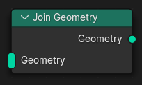
The Join Geometry node merges separately generated geometries into a single one. If the geometry inputs contain different types of data, the output will also contain different data types. |
|
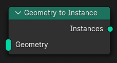
The Geometry to Instance node turns every connected input geometry into an instance. Visually, the node has a similar result as the Join Geometry Node, but it outputs the result as separate instances instead. The geometry data itself isn’t actually joined. |
|
The Spline Parameter node outputs how far along each spline a control point is. The Factor output is different from dividing the index by the total number of control points, because the control points might not be equally spaced along the curve. |
API#
- class pynodes.geosocks.Geometry(bsocket: bpy.types.NodeSocket)#
Bases:
pynodes.core.SocketRepresents a green ouput socket of a node, the base class of all geometry data socket
Initialization
- bl_idname = 'NodeSocketGeometry'#
- __getitem__(selection)#
- __mul__(other)#
- property selection#
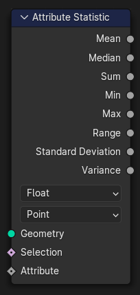
- float_statistic_on_points(attribute=0.0, selection=True)#
The Attribute Statistic node evaluates a field on a geometry and outputs a statistic about the entire data set.
Path#
Attribute > Attribute Statistic Node
Outputs:#
#0 mean: Float = 0.0#1 median: Float = 0.0#2 sum: Float = 0.0#3 min: Float = 0.0#4 max: Float = 0.0#5 range: Float = 0.0#6 standard_deviation: Float = 0.0#7 variance: Float = 0.0
- float_statistic_on_edges(attribute=0.0, selection=True)#
The Attribute Statistic node evaluates a field on a geometry and outputs a statistic about the entire data set.
Path#
Attribute > Attribute Statistic Node
Outputs:#
#0 mean: Float = 0.0#1 median: Float = 0.0#2 sum: Float = 0.0#3 min: Float = 0.0#4 max: Float = 0.0#5 range: Float = 0.0#6 standard_deviation: Float = 0.0#7 variance: Float = 0.0
- float_statistic_on_faces(attribute=0.0, selection=True)#
The Attribute Statistic node evaluates a field on a geometry and outputs a statistic about the entire data set.
Path#
Attribute > Attribute Statistic Node
Outputs:#
#0 mean: Float = 0.0#1 median: Float = 0.0#2 sum: Float = 0.0#3 min: Float = 0.0#4 max: Float = 0.0#5 range: Float = 0.0#6 standard_deviation: Float = 0.0#7 variance: Float = 0.0
- float_statistic_on_corners(attribute=0.0, selection=True)#
The Attribute Statistic node evaluates a field on a geometry and outputs a statistic about the entire data set.
Path#
Attribute > Attribute Statistic Node
Outputs:#
#0 mean: Float = 0.0#1 median: Float = 0.0#2 sum: Float = 0.0#3 min: Float = 0.0#4 max: Float = 0.0#5 range: Float = 0.0#6 standard_deviation: Float = 0.0#7 variance: Float = 0.0
- float_statistic_on_curves(attribute=0.0, selection=True)#
The Attribute Statistic node evaluates a field on a geometry and outputs a statistic about the entire data set.
Path#
Attribute > Attribute Statistic Node
Outputs:#
#0 mean: Float = 0.0#1 median: Float = 0.0#2 sum: Float = 0.0#3 min: Float = 0.0#4 max: Float = 0.0#5 range: Float = 0.0#6 standard_deviation: Float = 0.0#7 variance: Float = 0.0
- float_statistic_on_instances(attribute=0.0, selection=True)#
The Attribute Statistic node evaluates a field on a geometry and outputs a statistic about the entire data set.
Path#
Attribute > Attribute Statistic Node
Outputs:#
#0 mean: Float = 0.0#1 median: Float = 0.0#2 sum: Float = 0.0#3 min: Float = 0.0#4 max: Float = 0.0#5 range: Float = 0.0#6 standard_deviation: Float = 0.0#7 variance: Float = 0.0
- integer_statistic_on_points(attribute=0, selection=True)#
The Attribute Statistic node evaluates a field on a geometry and outputs a statistic about the entire data set.
Path#
Attribute > Attribute Statistic Node
Outputs:#
#0 mean: Float = 0.0#1 median: Float = 0.0#2 sum: Float = 0.0#3 min: Float = 0.0#4 max: Float = 0.0#5 range: Float = 0.0#6 standard_deviation: Float = 0.0#7 variance: Float = 0.0
- integer_statistic_on_edges(attribute=0, selection=True)#
The Attribute Statistic node evaluates a field on a geometry and outputs a statistic about the entire data set.
Path#
Attribute > Attribute Statistic Node
Outputs:#
#0 mean: Float = 0.0#1 median: Float = 0.0#2 sum: Float = 0.0#3 min: Float = 0.0#4 max: Float = 0.0#5 range: Float = 0.0#6 standard_deviation: Float = 0.0#7 variance: Float = 0.0
- integer_statistic_on_faces(attribute=0, selection=True)#
The Attribute Statistic node evaluates a field on a geometry and outputs a statistic about the entire data set.
Path#
Attribute > Attribute Statistic Node
Outputs:#
#0 mean: Float = 0.0#1 median: Float = 0.0#2 sum: Float = 0.0#3 min: Float = 0.0#4 max: Float = 0.0#5 range: Float = 0.0#6 standard_deviation: Float = 0.0#7 variance: Float = 0.0
- integer_statistic_on_corners(attribute=0, selection=True)#
The Attribute Statistic node evaluates a field on a geometry and outputs a statistic about the entire data set.
Path#
Attribute > Attribute Statistic Node
Outputs:#
#0 mean: Float = 0.0#1 median: Float = 0.0#2 sum: Float = 0.0#3 min: Float = 0.0#4 max: Float = 0.0#5 range: Float = 0.0#6 standard_deviation: Float = 0.0#7 variance: Float = 0.0
- integer_statistic_on_curves(attribute=0, selection=True)#
The Attribute Statistic node evaluates a field on a geometry and outputs a statistic about the entire data set.
Path#
Attribute > Attribute Statistic Node
Outputs:#
#0 mean: Float = 0.0#1 median: Float = 0.0#2 sum: Float = 0.0#3 min: Float = 0.0#4 max: Float = 0.0#5 range: Float = 0.0#6 standard_deviation: Float = 0.0#7 variance: Float = 0.0
- integer_statistic_on_instances(attribute=0, selection=True)#
The Attribute Statistic node evaluates a field on a geometry and outputs a statistic about the entire data set.
Path#
Attribute > Attribute Statistic Node
Outputs:#
#0 mean: Float = 0.0#1 median: Float = 0.0#2 sum: Float = 0.0#3 min: Float = 0.0#4 max: Float = 0.0#5 range: Float = 0.0#6 standard_deviation: Float = 0.0#7 variance: Float = 0.0
- vector_statistic_on_points(attribute=(0.0, 0.0, 0.0), selection=True)#
The Attribute Statistic node evaluates a field on a geometry and outputs a statistic about the entire data set.
Path#
Attribute > Attribute Statistic Node
Outputs:#
#8 mean: Vector = (0.0, 0.0, 0.0)#9 median: Vector = (0.0, 0.0, 0.0)#10 sum: Vector = (0.0, 0.0, 0.0)#11 min: Vector = (0.0, 0.0, 0.0)#12 max: Vector = (0.0, 0.0, 0.0)#13 range: Vector = (0.0, 0.0, 0.0)#14 standard_deviation: Vector = (0.0, 0.0, 0.0)#15 variance: Vector = (0.0, 0.0, 0.0)
- vector_statistic_on_edges(attribute=(0.0, 0.0, 0.0), selection=True)#
The Attribute Statistic node evaluates a field on a geometry and outputs a statistic about the entire data set.
Path#
Attribute > Attribute Statistic Node
Outputs:#
#8 mean: Vector = (0.0, 0.0, 0.0)#9 median: Vector = (0.0, 0.0, 0.0)#10 sum: Vector = (0.0, 0.0, 0.0)#11 min: Vector = (0.0, 0.0, 0.0)#12 max: Vector = (0.0, 0.0, 0.0)#13 range: Vector = (0.0, 0.0, 0.0)#14 standard_deviation: Vector = (0.0, 0.0, 0.0)#15 variance: Vector = (0.0, 0.0, 0.0)
- vector_statistic_on_faces(attribute=(0.0, 0.0, 0.0), selection=True)#
The Attribute Statistic node evaluates a field on a geometry and outputs a statistic about the entire data set.
Path#
Attribute > Attribute Statistic Node
Outputs:#
#8 mean: Vector = (0.0, 0.0, 0.0)#9 median: Vector = (0.0, 0.0, 0.0)#10 sum: Vector = (0.0, 0.0, 0.0)#11 min: Vector = (0.0, 0.0, 0.0)#12 max: Vector = (0.0, 0.0, 0.0)#13 range: Vector = (0.0, 0.0, 0.0)#14 standard_deviation: Vector = (0.0, 0.0, 0.0)#15 variance: Vector = (0.0, 0.0, 0.0)
- vector_statistic_on_corners(attribute=(0.0, 0.0, 0.0), selection=True)#
The Attribute Statistic node evaluates a field on a geometry and outputs a statistic about the entire data set.
Path#
Attribute > Attribute Statistic Node
Outputs:#
#8 mean: Vector = (0.0, 0.0, 0.0)#9 median: Vector = (0.0, 0.0, 0.0)#10 sum: Vector = (0.0, 0.0, 0.0)#11 min: Vector = (0.0, 0.0, 0.0)#12 max: Vector = (0.0, 0.0, 0.0)#13 range: Vector = (0.0, 0.0, 0.0)#14 standard_deviation: Vector = (0.0, 0.0, 0.0)#15 variance: Vector = (0.0, 0.0, 0.0)
- vector_statistic_on_curves(attribute=(0.0, 0.0, 0.0), selection=True)#
The Attribute Statistic node evaluates a field on a geometry and outputs a statistic about the entire data set.
Path#
Attribute > Attribute Statistic Node
Outputs:#
#8 mean: Vector = (0.0, 0.0, 0.0)#9 median: Vector = (0.0, 0.0, 0.0)#10 sum: Vector = (0.0, 0.0, 0.0)#11 min: Vector = (0.0, 0.0, 0.0)#12 max: Vector = (0.0, 0.0, 0.0)#13 range: Vector = (0.0, 0.0, 0.0)#14 standard_deviation: Vector = (0.0, 0.0, 0.0)#15 variance: Vector = (0.0, 0.0, 0.0)
- vector_statistic_on_instances(attribute=(0.0, 0.0, 0.0), selection=True)#
The Attribute Statistic node evaluates a field on a geometry and outputs a statistic about the entire data set.
Path#
Attribute > Attribute Statistic Node
Outputs:#
#8 mean: Vector = (0.0, 0.0, 0.0)#9 median: Vector = (0.0, 0.0, 0.0)#10 sum: Vector = (0.0, 0.0, 0.0)#11 min: Vector = (0.0, 0.0, 0.0)#12 max: Vector = (0.0, 0.0, 0.0)#13 range: Vector = (0.0, 0.0, 0.0)#14 standard_deviation: Vector = (0.0, 0.0, 0.0)#15 variance: Vector = (0.0, 0.0, 0.0)
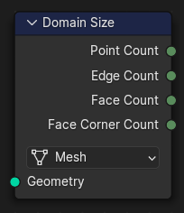
- domain_size(component='MESH')#
The Domain Size outputs the size of an attribute domain on the selected geometry type, for example, the number of edges in a mesh, or the number of points in a point cloud.
Path#
Attribute > Domain Size Node
Properties#
component:MESH,POINTCLOUD,CURVE,INSTANCES
Outputs:#
#0 point_count: Integer = 0#1 edge_count: Integer = 0#2 face_count: Integer = 0#3 face_corner_count: Integer = 0#4 spline_count: Integer = 0#5 instance_count: Integer = 0
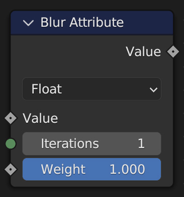
- static blur_float_attribute(value_float=0.0, iterations=1, weight=1.0)#
The Blur Attribute node smooths attribute values between neighboring geometry elements.
Path#
Attribute > Blur Attribute Node
Outputs:#
#0 value_float: Float = 0.0
- static blur_integer_attribute(value_int=0, iterations=1, weight=1.0)#
The Blur Attribute node smooths attribute values between neighboring geometry elements.
Path#
Attribute > Blur Attribute Node
Outputs:#
#1 value_int: Integer = 0
- static blur_vector_attribute(value_vector=(0.0, 0.0, 0.0), iterations=1, weight=1.0)#
The Blur Attribute node smooths attribute values between neighboring geometry elements.
Path#
Attribute > Blur Attribute Node
Outputs:#
#2 value_vector: Vector = (0.0, 0.0, 0.0)
- static blur_color_attribute(value_color=(0.0, 0.0, 0.0, 0.0), iterations=1, weight=1.0)#
The Blur Attribute node smooths attribute values between neighboring geometry elements.
Path#
Attribute > Blur Attribute Node
Outputs:#
#3 value_color: Color = (0.0, 0.0, 0.0, 0.0)
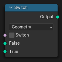
- switch(switch=False, true_geometry=None)#
The Switch node outputs one of two inputs depending on a condition. Only the input that is passed through the node is computed.
In-Place Operation
Path#
Utilities > Switch Node
Outputs:#
#6 output_006: Geometry = None
- capture_vector_on_points(value=(0.0, 0.0, 0.0))#
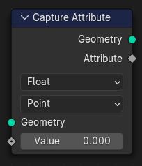
The Capture Attribute node stores the result of a field on a geometry, and outputs the data as a node socket so it can be used by other nodes.
In-Place Operation
Path#
Attribute > Capture Attribute Node
Outputs:#
#0 geometry: Geometry = None#1 attribute: Vector = (0.0, 0.0, 0.0)
- capture_vector_on_edges(value=(0.0, 0.0, 0.0))#
The Capture Attribute node stores the result of a field on a geometry, and outputs the data as a node socket so it can be used by other nodes.
In-Place Operation
Path#
Attribute > Capture Attribute Node
Outputs:#
#0 geometry: Geometry = None#1 attribute: Vector = (0.0, 0.0, 0.0)
- capture_vector_on_faces(value=(0.0, 0.0, 0.0))#
The Capture Attribute node stores the result of a field on a geometry, and outputs the data as a node socket so it can be used by other nodes.
In-Place Operation
Path#
Attribute > Capture Attribute Node
Outputs:#
#0 geometry: Geometry = None#1 attribute: Vector = (0.0, 0.0, 0.0)
- capture_vector_on_corners(value=(0.0, 0.0, 0.0))#
The Capture Attribute node stores the result of a field on a geometry, and outputs the data as a node socket so it can be used by other nodes.
In-Place Operation
Path#
Attribute > Capture Attribute Node
Outputs:#
#0 geometry: Geometry = None#1 attribute: Vector = (0.0, 0.0, 0.0)
- capture_vector_on_curves(value=(0.0, 0.0, 0.0))#
The Capture Attribute node stores the result of a field on a geometry, and outputs the data as a node socket so it can be used by other nodes.
In-Place Operation
Path#
Attribute > Capture Attribute Node
Outputs:#
#0 geometry: Geometry = None#1 attribute: Vector = (0.0, 0.0, 0.0)
- capture_vector_on_instances(value=(0.0, 0.0, 0.0))#
The Capture Attribute node stores the result of a field on a geometry, and outputs the data as a node socket so it can be used by other nodes.
In-Place Operation
Path#
Attribute > Capture Attribute Node
Outputs:#
#0 geometry: Geometry = None#1 attribute: Vector = (0.0, 0.0, 0.0)
- capture_float_on_points(value=0.0)#
The Capture Attribute node stores the result of a field on a geometry, and outputs the data as a node socket so it can be used by other nodes.
In-Place Operation
Path#
Attribute > Capture Attribute Node
Outputs:#
#0 geometry: Geometry = None#2 attribute: Float = 0.0
- capture_float_on_edges(value=0.0)#
The Capture Attribute node stores the result of a field on a geometry, and outputs the data as a node socket so it can be used by other nodes.
In-Place Operation
Path#
Attribute > Capture Attribute Node
Outputs:#
#0 geometry: Geometry = None#2 attribute: Float = 0.0
- capture_float_on_faces(value=0.0)#
The Capture Attribute node stores the result of a field on a geometry, and outputs the data as a node socket so it can be used by other nodes.
In-Place Operation
Path#
Attribute > Capture Attribute Node
Outputs:#
#0 geometry: Geometry = None#2 attribute: Float = 0.0
- capture_float_on_corners(value=0.0)#
The Capture Attribute node stores the result of a field on a geometry, and outputs the data as a node socket so it can be used by other nodes.
In-Place Operation
Path#
Attribute > Capture Attribute Node
Outputs:#
#0 geometry: Geometry = None#2 attribute: Float = 0.0
- capture_float_on_curves(value=0.0)#
The Capture Attribute node stores the result of a field on a geometry, and outputs the data as a node socket so it can be used by other nodes.
In-Place Operation
Path#
Attribute > Capture Attribute Node
Outputs:#
#0 geometry: Geometry = None#2 attribute: Float = 0.0
- capture_float_on_instances(value=0.0)#
The Capture Attribute node stores the result of a field on a geometry, and outputs the data as a node socket so it can be used by other nodes.
In-Place Operation
Path#
Attribute > Capture Attribute Node
Outputs:#
#0 geometry: Geometry = None#2 attribute: Float = 0.0
- capture_color_on_points(value=(0.0, 0.0, 0.0, 0.0))#
The Capture Attribute node stores the result of a field on a geometry, and outputs the data as a node socket so it can be used by other nodes.
In-Place Operation
Path#
Attribute > Capture Attribute Node
Outputs:#
#0 geometry: Geometry = None#3 attribute: Color = (0.0, 0.0, 0.0, 0.0)
- capture_color_on_edges(value=(0.0, 0.0, 0.0, 0.0))#
The Capture Attribute node stores the result of a field on a geometry, and outputs the data as a node socket so it can be used by other nodes.
In-Place Operation
Path#
Attribute > Capture Attribute Node
Outputs:#
#0 geometry: Geometry = None#3 attribute: Color = (0.0, 0.0, 0.0, 0.0)
- capture_color_on_faces(value=(0.0, 0.0, 0.0, 0.0))#
The Capture Attribute node stores the result of a field on a geometry, and outputs the data as a node socket so it can be used by other nodes.
In-Place Operation
Path#
Attribute > Capture Attribute Node
Outputs:#
#0 geometry: Geometry = None#3 attribute: Color = (0.0, 0.0, 0.0, 0.0)
- capture_color_on_corners(value=(0.0, 0.0, 0.0, 0.0))#
The Capture Attribute node stores the result of a field on a geometry, and outputs the data as a node socket so it can be used by other nodes.
In-Place Operation
Path#
Attribute > Capture Attribute Node
Outputs:#
#0 geometry: Geometry = None#3 attribute: Color = (0.0, 0.0, 0.0, 0.0)
- capture_color_on_curves(value=(0.0, 0.0, 0.0, 0.0))#
The Capture Attribute node stores the result of a field on a geometry, and outputs the data as a node socket so it can be used by other nodes.
In-Place Operation
Path#
Attribute > Capture Attribute Node
Outputs:#
#0 geometry: Geometry = None#3 attribute: Color = (0.0, 0.0, 0.0, 0.0)
- capture_color_on_instances(value=(0.0, 0.0, 0.0, 0.0))#
The Capture Attribute node stores the result of a field on a geometry, and outputs the data as a node socket so it can be used by other nodes.
In-Place Operation
Path#
Attribute > Capture Attribute Node
Outputs:#
#0 geometry: Geometry = None#3 attribute: Color = (0.0, 0.0, 0.0, 0.0)
- capture_boolean_on_points(value=False)#
The Capture Attribute node stores the result of a field on a geometry, and outputs the data as a node socket so it can be used by other nodes.
In-Place Operation
Path#
Attribute > Capture Attribute Node
Outputs:#
#0 geometry: Geometry = None#4 attribute: Boolean = False
- capture_boolean_on_edges(value=False)#
The Capture Attribute node stores the result of a field on a geometry, and outputs the data as a node socket so it can be used by other nodes.
In-Place Operation
Path#
Attribute > Capture Attribute Node
Outputs:#
#0 geometry: Geometry = None#4 attribute: Boolean = False
- capture_boolean_on_faces(value=False)#
The Capture Attribute node stores the result of a field on a geometry, and outputs the data as a node socket so it can be used by other nodes.
In-Place Operation
Path#
Attribute > Capture Attribute Node
Outputs:#
#0 geometry: Geometry = None#4 attribute: Boolean = False
- capture_boolean_on_corners(value=False)#
The Capture Attribute node stores the result of a field on a geometry, and outputs the data as a node socket so it can be used by other nodes.
In-Place Operation
Path#
Attribute > Capture Attribute Node
Outputs:#
#0 geometry: Geometry = None#4 attribute: Boolean = False
- capture_boolean_on_curves(value=False)#
The Capture Attribute node stores the result of a field on a geometry, and outputs the data as a node socket so it can be used by other nodes.
In-Place Operation
Path#
Attribute > Capture Attribute Node
Outputs:#
#0 geometry: Geometry = None#4 attribute: Boolean = False
- capture_boolean_on_instances(value=False)#
The Capture Attribute node stores the result of a field on a geometry, and outputs the data as a node socket so it can be used by other nodes.
In-Place Operation
Path#
Attribute > Capture Attribute Node
Outputs:#
#0 geometry: Geometry = None#4 attribute: Boolean = False
- capture_integer_on_points(value=0)#
The Capture Attribute node stores the result of a field on a geometry, and outputs the data as a node socket so it can be used by other nodes.
In-Place Operation
Path#
Attribute > Capture Attribute Node
Outputs:#
#0 geometry: Geometry = None#5 attribute: Integer = 0
- capture_integer_on_edges(value=0)#
The Capture Attribute node stores the result of a field on a geometry, and outputs the data as a node socket so it can be used by other nodes.
In-Place Operation
Path#
Attribute > Capture Attribute Node
Outputs:#
#0 geometry: Geometry = None#5 attribute: Integer = 0
- capture_integer_on_faces(value=0)#
The Capture Attribute node stores the result of a field on a geometry, and outputs the data as a node socket so it can be used by other nodes.
In-Place Operation
Path#
Attribute > Capture Attribute Node
Outputs:#
#0 geometry: Geometry = None#5 attribute: Integer = 0
- capture_integer_on_corners(value=0)#
The Capture Attribute node stores the result of a field on a geometry, and outputs the data as a node socket so it can be used by other nodes.
In-Place Operation
Path#
Attribute > Capture Attribute Node
Outputs:#
#0 geometry: Geometry = None#5 attribute: Integer = 0
- capture_integer_on_curves(value=0)#
The Capture Attribute node stores the result of a field on a geometry, and outputs the data as a node socket so it can be used by other nodes.
In-Place Operation
Path#
Attribute > Capture Attribute Node
Outputs:#
#0 geometry: Geometry = None#5 attribute: Integer = 0
- capture_integer_on_instances(value=0)#
The Capture Attribute node stores the result of a field on a geometry, and outputs the data as a node socket so it can be used by other nodes.
In-Place Operation
Path#
Attribute > Capture Attribute Node
Outputs:#
#0 geometry: Geometry = None#5 attribute: Integer = 0
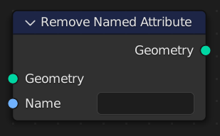
- remove_attribute(name='')#
The Remove Named Attribute node deletes an attribute with a certain name from its geometry input. Any attribute that exists on geometry data will be automatically propagated when the geometry storing it is changed, which can be an expensive operation, so using this node can be a simple way to optimize the performance of a geometry node tree or even to lower the memory usage of the entire scene.
In-Place Operation
Path#
Attribute > Remove Named Attribute Node
Outputs:#
#0 geometry: Geometry = None
- remove_attributes(*names: list[str])#
The Remove Named Attribute node deletes an attribute with a certain name from its geometry input. Any attribute that exists on geometry data will be automatically propagated when the geometry storing it is changed, which can be an expensive operation, so using this node can be a simple way to optimize the performance of a geometry node tree or even to lower the memory usage of the entire scene.
In-Place Operation
Path#
Attribute > Remove Named Attribute Node
Outputs:#
#0 geometry: Geometry = None
- _store_named_attribute(data_type='FLOAT', domain='POINT', selection=True, name='', value_vector=(0.0, 0.0, 0.0), value_float=0.0, value_color=(0.0, 0.0, 0.0, 0.0), value_bool=False, value_int=0)#
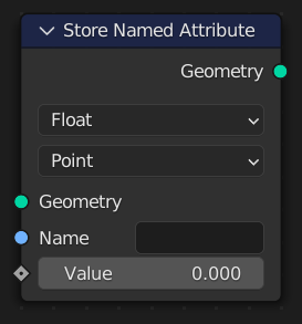
- store_named_attribute(name: str, value, domain='POINT', selection=True)#
The Store Named Attribute node stores the result of a field on a geometry as an attribute with the specified name. If the attribute already exists, the data type and domain will be updated to the values chosen in the node. However, keep in mind that the domain and data type of Built-In Attributes cannot be changed.
In-Place Operation
Path#
Attribute > Store Named Attribute Node
Properties#
data_type:FLOAT,INT,FLOAT_VECTOR,FLOAT_COLOR,BYTE_COLOR,BOOLEAN,FLOAT2domain:POINT,EDGE,FACE,CORNER,CURVE,INSTANCE
Outputs:#
#0 geometry: Geometry = None
- store_integer(domain='POINT', selection=True, **kwargs)#
The Store Named Attribute node stores the result of a field on a geometry as an attribute with the specified name. If the attribute already exists, the data type and domain will be updated to the values chosen in the node. However, keep in mind that the domain and data type of Built-In Attributes cannot be changed.
In-Place Operation
Path#
Attribute > Store Named Attribute Node
- store_float(domain='POINT', selection=True, **kwargs)#
The Store Named Attribute node stores the result of a field on a geometry as an attribute with the specified name. If the attribute already exists, the data type and domain will be updated to the values chosen in the node. However, keep in mind that the domain and data type of Built-In Attributes cannot be changed.
In-Place Operation
Path#
Attribute > Store Named Attribute Node
- store_boolean(domain='POINT', selection=True, **kwargs)#
The Store Named Attribute node stores the result of a field on a geometry as an attribute with the specified name. If the attribute already exists, the data type and domain will be updated to the values chosen in the node. However, keep in mind that the domain and data type of Built-In Attributes cannot be changed.
In-Place Operation
Path#
Attribute > Store Named Attribute Node
- store_vector(domain='POINT', selection=True, **kwargs)#
The Store Named Attribute node stores the result of a field on a geometry as an attribute with the specified name. If the attribute already exists, the data type and domain will be updated to the values chosen in the node. However, keep in mind that the domain and data type of Built-In Attributes cannot be changed.
In-Place Operation
Path#
Attribute > Store Named Attribute Node
- store_named_attributes(data: dict[str], domain='POINT', selection=True)#
The Store Named Attribute node stores the result of a field on a geometry as an attribute with the specified name. If the attribute already exists, the data type and domain will be updated to the values chosen in the node. However, keep in mind that the domain and data type of Built-In Attributes cannot be changed.
In-Place Operation
Path#
Attribute > Store Named Attribute Node
Properties#
data_type:FLOAT,INT,FLOAT_VECTOR,FLOAT_COLOR,BYTE_COLOR,BOOLEAN,FLOAT2domain:POINT,EDGE,FACE,CORNER,CURVE,INSTANCE
Outputs:#
#0 geometry: Geometry = None
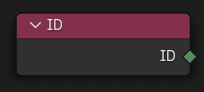
- property ID#
The ID node gives an integer value indicating the stable random identifier of each element on the point domain, which is stored in the id attribute.
Path#
Geometry > Read > ID Node
Outputs:#
#0 id: Integer = 0
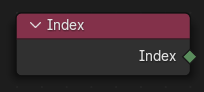
- property index#
The Index node gives an integer value indicating the position of each element in the list, starting at zero. This depends on the internal order of the data in the geometry, which is not necessarily visible in the 3D Viewport. However, the index value is visible in the left-most column in the Spreadsheet Editor.
Path#
Geometry > Read > Index Node
Outputs:#
#0 index: Integer = 0
- static named_attribute_vector(name='')#
The Named Attribute node outputs the data of an attribute based on the context of where it is connected (the Field Context).
Path#
Geometry > Read > Named Attribute Node
Outputs:#
#0 attribute_vector: Vector = (0.0, 0.0, 0.0)#5 exists: Boolean = False
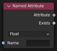
- static named_attribute_float(name='')#
The Named Attribute node outputs the data of an attribute based on the context of where it is connected (the Field Context).
Path#
Geometry > Read > Named Attribute Node
Outputs:#
#1 attribute_float: Float = 0.0#5 exists: Boolean = False
- static named_attribute_color(name='')#
The Named Attribute node outputs the data of an attribute based on the context of where it is connected (the Field Context).
Path#
Geometry > Read > Named Attribute Node
Outputs:#
#2 attribute_color: Color = (0.0, 0.0, 0.0, 0.0)#5 exists: Boolean = False
- static named_attribute_boolean(name='')#
The Named Attribute node outputs the data of an attribute based on the context of where it is connected (the Field Context).
Path#
Geometry > Read > Named Attribute Node
Outputs:#
#3 attribute_bool: Boolean = False#5 exists: Boolean = False
- static named_attribute_integer(name='')#
The Named Attribute node outputs the data of an attribute based on the context of where it is connected (the Field Context).
Path#
Geometry > Read > Named Attribute Node
Outputs:#
#4 attribute_int: Integer = 0#5 exists: Boolean = False
- property normal#
The Normal node returns a vector for each evaluated point indicating the normal direction. The output can depend on the attribute domain used in the node evaluating the field, but the output is always a normalized unit vector.
Path#
Geometry > Read > Normal Node
Outputs:#
#0 normal: Vector = (0.0, 0.0, 0.0)

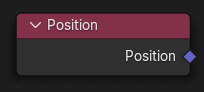
- property position#
The Position node outputs a vector of each point of the geometry the node is connected to.
Path#
Geometry > Read > Position Node
Outputs:#
#0 position: Vector = (0.0, 0.0, 0.0)
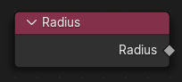
- property radius#
The Radius node outputs the radius value at each point on the evaluated geometry. For curves, this value is used for things like determining the size of the mesh created in the Curve to Mesh node. For point clouds, the value is used for the display size of the point in the viewport.
Path#
Geometry > Read > Radius Node
Outputs:#
#0 radius: Float = 1.0
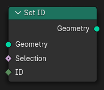
- set_id(id: pynodes.datasocks.Integer = None, selection=True)#
The Set ID node fills the id attribute on the input geometry. If the attribute does not exist yet, it will be created with a default value of zero. The ID is also created by the Distribute Points on Faces, and it is used in the Random Value Node and other nodes if it exists.
In-Place Operation
Path#
Geometry > Write > Set ID Node
Outputs:#
#0 geometry: Geometry = None
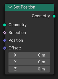
- set_position(position: pynodes.datasocks.Vector = None, offset=(0.0, 0.0, 0.0), selection=True)#
The Set Position node controls the location of each point, the same way as controlling the position attribute. If the input geometry contains instances, this node will affect the location of the origin of each instance.
In-Place Operation
Path#
Geometry > Write > Set Position Node
Outputs:#
#0 geometry: Geometry = None
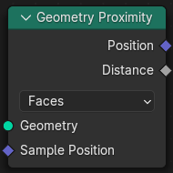
- proximity(target_element='FACES', source_position: pynodes.datasocks.Vector = None)#
The Geometry Proximity node computes the closest location on the target geometry.
Path#
Geometry > Sample > Geometry Proximity Node
Properties#
target_element:FACES,POINTS,EDGES
Outputs:#
#0 position: Vector = (0.0, 0.0, 0.0)#1 distance: Float = 0.0
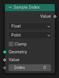
- sample_index(data_type='FLOAT', domain='POINT', clamp=False, value_float=0.0, value_int=0, value_vector=(0.0, 0.0, 0.0), value_color=(0.0, 0.0, 0.0, 0.0), value_bool=False, index=0)#
The Sample Index node retrieves values from a source geometry at a specific index.
Path#
Geometry > Sample > Sample Index Node
Properties#
data_type:FLOAT,INT,FLOAT_VECTOR,FLOAT_COLOR,BOOLEANdomain:POINT,EDGE,FACE,CORNER,CURVE,INSTANCE
Outputs:#
#0 value_float: Float = 0.0#1 value_int: Integer = 0#2 value_vector: Vector = (0.0, 0.0, 0.0)#3 value_color: Color = (0.0, 0.0, 0.0, 0.0)#4 value_bool: Boolean = False
- sample_float_at_index(value=0.0, index=0, domain='POINT', clamp=False)#
The Sample Index node retrieves values from a source geometry at a specific index.
Path#
Geometry > Sample > Sample Index Node
Properties#
domain:POINT,EDGE,FACE,CORNER,CURVE,INSTANCE
Outputs:#
#0 value_float: Float = 0.0
- sample_integer_at_index(value=0, index=0, domain='POINT', clamp=False)#
The Sample Index node retrieves values from a source geometry at a specific index.
Path#
Geometry > Sample > Sample Index Node
Properties#
domain:POINT,EDGE,FACE,CORNER,CURVE,INSTANCE
Outputs:#
#1 value_int: Integer = 0
- sample_vector_at_index(value=(0.0, 0.0, 0.0), index=0, domain='POINT', clamp=False)#
The Sample Index node retrieves values from a source geometry at a specific index.
Path#
Geometry > Sample > Sample Index Node
Properties#
domain:POINT,EDGE,FACE,CORNER,CURVE,INSTANCE
Outputs:#
#2 value_vector: Vector = (0.0, 0.0, 0.0)
- sample_color_at_index(value=(0.0, 0.0, 0.0, 0.0), index=0, domain='POINT', clamp=False)#
The Sample Index node retrieves values from a source geometry at a specific index.
Path#
Geometry > Sample > Sample Index Node
Properties#
domain:POINT,EDGE,FACE,CORNER,CURVE,INSTANCE
Outputs:#
#3 value_color: Color = (0.0, 0.0, 0.0, 0.0)
- sample_boolean_at_index(value=False, index=0, domain='POINT', clamp=False)#
The Sample Index node retrieves values from a source geometry at a specific index.
Path#
Geometry > Sample > Sample Index Node
Properties#
domain:POINT,EDGE,FACE,CORNER,CURVE,INSTANCE
Outputs:#
#4 value_bool: Boolean = False
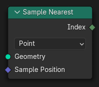
- sample_nearest(sample_position: pynodes.datasocks.Vector = None, domain='POINT')#
The Sample Nearest node retrieves the index of the geometry element in its input geometry that is closest to the input position. This node is similar to the Geometry Proximity Node, but it outputs the index of the closest element instead of its distance from the current location.
Path#
Geometry > Sample > Sample Nearest Node
Properties#
domain:POINT,EDGE,FACE,CORNER
Outputs:#
#0 index: Integer = 0
- sample_nearest_on_points(sample_position: pynodes.datasocks.Vector = None)#
The Sample Nearest node retrieves the index of the geometry element in its input geometry that is closest to the input position. This node is similar to the Geometry Proximity Node, but it outputs the index of the closest element instead of its distance from the current location.
Path#
Geometry > Sample > Sample Nearest Node
Properties#
domain:POINT,EDGE,FACE,CORNER
Outputs:#
#0 index: Integer = 0
- sample_nearest_on_edges(sample_position: pynodes.datasocks.Vector = None)#
The Sample Nearest node retrieves the index of the geometry element in its input geometry that is closest to the input position. This node is similar to the Geometry Proximity Node, but it outputs the index of the closest element instead of its distance from the current location.
Path#
Geometry > Sample > Sample Nearest Node
Properties#
domain:POINT,EDGE,FACE,CORNER
Outputs:#
#0 index: Integer = 0
- sample_nearest_on_faces(sample_position: pynodes.datasocks.Vector = None)#
The Sample Nearest node retrieves the index of the geometry element in its input geometry that is closest to the input position. This node is similar to the Geometry Proximity Node, but it outputs the index of the closest element instead of its distance from the current location.
Path#
Geometry > Sample > Sample Nearest Node
Properties#
domain:POINT,EDGE,FACE,CORNER
Outputs:#
#0 index: Integer = 0
- sample_nearest_on_corners(sample_position: pynodes.datasocks.Vector = None)#
The Sample Nearest node retrieves the index of the geometry element in its input geometry that is closest to the input position. This node is similar to the Geometry Proximity Node, but it outputs the index of the closest element instead of its distance from the current location.
Path#
Geometry > Sample > Sample Nearest Node
Properties#
domain:POINT,EDGE,FACE,CORNER
Outputs:#
#0 index: Integer = 0
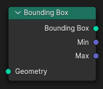
- bounding_box()#
The Bounding Box node creates a box mesh with the minimum volume that encapsulates the geometry of the input. The node also can output the vector positions of the bounding dimensions.
Path#
Geometry > Operations > Bounding Box Node
Outputs:#
#0 bounding_box: Geometry = None#1 min: Vector = (0.0, 0.0, 0.0)#2 max: Vector = (0.0, 0.0, 0.0)
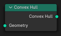
- convex_hull()#
The Convex Hull node outputs a convex mesh that is enclosing all points in the input geometry.
Path#
Geometry > Operations > Convex Hull Node
Outputs:#
#0 convex_hull: Geometry = None
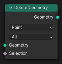
- delete(domain='POINT', mode='ALL', selection=True)#
The Delete Geometry node removes the selected part of a geometry. It behaves similarly to the Delete tool in Edit Mode. The type of elements to be deleted can be specified with the domain and mode properties.
In-Place Operation
Path#
Geometry > Operations > Delete Geometry Node
Properties#
domain:POINT,EDGE,FACE,CURVE,INSTANCEmode:ALL,EDGE_FACE,ONLY_FACE
Outputs:#
#0 geometry: Geometry = None
- delete_points(mode='ALL', selection=True)#
The Delete Geometry node removes the selected part of a geometry. It behaves similarly to the Delete tool in Edit Mode. The type of elements to be deleted can be specified with the domain and mode properties.
In-Place Operation
Path#
Geometry > Operations > Delete Geometry Node
Properties#
mode:ALL,EDGE_FACE,ONLY_FACE
Outputs:#
#0 geometry: Geometry = None
- delete_edges(mode='ALL', selection=True)#
The Delete Geometry node removes the selected part of a geometry. It behaves similarly to the Delete tool in Edit Mode. The type of elements to be deleted can be specified with the domain and mode properties.
In-Place Operation
Path#
Geometry > Operations > Delete Geometry Node
Properties#
mode:ALL,EDGE_FACE,ONLY_FACE
Outputs:#
#0 geometry: Geometry = None
- delete_faces(mode='ALL', selection=True)#
The Delete Geometry node removes the selected part of a geometry. It behaves similarly to the Delete tool in Edit Mode. The type of elements to be deleted can be specified with the domain and mode properties.
In-Place Operation
Path#
Geometry > Operations > Delete Geometry Node
Properties#
mode:ALL,EDGE_FACE,ONLY_FACE
Outputs:#
#0 geometry: Geometry = None
- delete_curves(mode='ALL', selection=True)#
The Delete Geometry node removes the selected part of a geometry. It behaves similarly to the Delete tool in Edit Mode. The type of elements to be deleted can be specified with the domain and mode properties.
In-Place Operation
Path#
Geometry > Operations > Delete Geometry Node
Properties#
mode:ALL,EDGE_FACE,ONLY_FACE
Outputs:#
#0 geometry: Geometry = None
- delete_instances(mode='ALL', selection=True)#
The Delete Geometry node removes the selected part of a geometry. It behaves similarly to the Delete tool in Edit Mode. The type of elements to be deleted can be specified with the domain and mode properties.
In-Place Operation
Path#
Geometry > Operations > Delete Geometry Node
Properties#
mode:ALL,EDGE_FACE,ONLY_FACE
Outputs:#
#0 geometry: Geometry = None
- duplicate_elements(amount=1, domain='POINT', selection=True)#
The Duplicate Elements node creates a new geometry with the specified elements from the input duplicated an arbitrary number of times. The positions of elements are not changed, so all of the duplicates will be at the exact same location.
Path#
Geometry > Operations > Duplicate Elements Node
Properties#
domain:POINT,EDGE,FACE,SPLINE,INSTANCE
Outputs:#
#0 geometry: Geometry = None#1 duplicate_index: Integer = 0
- merge_by_distance(distance=0.001, mode='ALL', selection=True)#
The Merge by Distance node merges selected mesh vertices or point cloud points within a given distance, merging surrounding geometry where necessary. This operation is similar to the Merge by Distance operator or the Weld Modifier.
Path#
Geometry > Operations > Merge by Distance Node
Properties#
mode:ALL,CONNECTED
Outputs:#
#0 geometry: Geometry = None
- transform(translation=(0.0, 0.0, 0.0), rotation=(0.0, 0.0, 0.0), scale=(1.0, 1.0, 1.0))#
The Transform Geometry Node allows you to move, rotate or scale the geometry. The transformation is applied to the entire geometry, and not per element. The Set Position Node is used for moving individual points of a geometry. For transforming instances individually, the instance translate, rotate, or scale nodes can be used.
In-Place Operation
Path#
Geometry > Operations > Transform Geometry Node
Outputs:#
#0 geometry: Geometry = None
- translate(translation=(0.0, 0.0, 0.0))#
The Transform Geometry Node allows you to move, rotate or scale the geometry. The transformation is applied to the entire geometry, and not per element. The Set Position Node is used for moving individual points of a geometry. For transforming instances individually, the instance translate, rotate, or scale nodes can be used.
In-Place Operation
Path#
Geometry > Operations > Transform Geometry Node
Outputs:#
#0 geometry: Geometry = None
- rotate(rotation=(0.0, 0.0, 0.0))#
The Transform Geometry Node allows you to move, rotate or scale the geometry. The transformation is applied to the entire geometry, and not per element. The Set Position Node is used for moving individual points of a geometry. For transforming instances individually, the instance translate, rotate, or scale nodes can be used.
In-Place Operation
Path#
Geometry > Operations > Transform Geometry Node
Outputs:#
#0 geometry: Geometry = None
- scale(scale=(1.0, 1.0, 1.0))#
The Transform Geometry Node allows you to move, rotate or scale the geometry. The transformation is applied to the entire geometry, and not per element. The Set Position Node is used for moving individual points of a geometry. For transforming instances individually, the instance translate, rotate, or scale nodes can be used.
In-Place Operation
Path#
Geometry > Operations > Transform Geometry Node
Outputs:#
#0 geometry: Geometry = None
- separate_components()#
The Separate Components node splits a geometry into a separate output for each type of data in the geometry.
Path#
Geometry > Operations > Separate Components Node
Outputs:#
#0 mesh: Geometry = None#1 curve: Geometry = None#2 point_cloud: Geometry = None#3 volume: Geometry = None#4 instances: Geometry = None
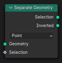
- separate(selection=True, domain='POINT')#
The Separate Geometry node produces two geometry outputs. Based on the Selection input, the input geometry is split between the two outputs.
Path#
Geometry > Operations > Separate Geometry Node
Properties#
domain:POINT,EDGE,FACE,CURVE,INSTANCE
Outputs:#
#0 selection: Geometry = None#1 inverted: Geometry = None
- separate_edges(selection=True)#
The Separate Geometry node produces two geometry outputs. Based on the Selection input, the input geometry is split between the two outputs.
Path#
Geometry > Operations > Separate Geometry Node
Outputs:#
#0 selection: Geometry = None#1 inverted: Geometry = None
- separate_faces(selection=True)#
The Separate Geometry node produces two geometry outputs. Based on the Selection input, the input geometry is split between the two outputs.
Path#
Geometry > Operations > Separate Geometry Node
Outputs:#
#0 selection: Geometry = None#1 inverted: Geometry = None
- separate_curves(selection=True)#
The Separate Geometry node produces two geometry outputs. Based on the Selection input, the input geometry is split between the two outputs.
Path#
Geometry > Operations > Separate Geometry Node
Outputs:#
#0 selection: Geometry = None#1 inverted: Geometry = None
- separate_instances(selection=True)#
The Separate Geometry node produces two geometry outputs. Based on the Selection input, the input geometry is split between the two outputs.
Path#
Geometry > Operations > Separate Geometry Node
Outputs:#
#0 selection: Geometry = None#1 inverted: Geometry = None
- select(selection=True, domain='POINT')#
The Separate Geometry node produces two geometry outputs. Based on the Selection input, the input geometry is split between the two outputs.
In-Place Operation
Path#
Geometry > Operations > Separate Geometry Node
Properties#
domain:POINT,EDGE,FACE,CURVE,INSTANCE
- select_points(selection=True)#
The Separate Geometry node produces two geometry outputs. Based on the Selection input, the input geometry is split between the two outputs.
In-Place Operation
Path#
Geometry > Operations > Separate Geometry Node
Outputs:#
#0 selection: Geometry = None#1 inverted: Geometry = None
- select_edges(selection=True)#
The Separate Geometry node produces two geometry outputs. Based on the Selection input, the input geometry is split between the two outputs.
In-Place Operation
Path#
Geometry > Operations > Separate Geometry Node
Outputs:#
#0 selection: Geometry = None#1 inverted: Geometry = None
- select_faces(selection=True)#
The Separate Geometry node produces two geometry outputs. Based on the Selection input, the input geometry is split between the two outputs.
In-Place Operation
Path#
Geometry > Operations > Separate Geometry Node
Outputs:#
#0 selection: Geometry = None#1 inverted: Geometry = None
- select_curves(selection=True)#
The Separate Geometry node produces two geometry outputs. Based on the Selection input, the input geometry is split between the two outputs.
In-Place Operation
Path#
Geometry > Operations > Separate Geometry Node
Outputs:#
#0 selection: Geometry = None#1 inverted: Geometry = None
- select_instances(selection=True)#
The Separate Geometry node produces two geometry outputs. Based on the Selection input, the input geometry is split between the two outputs.
In-Place Operation
Path#
Geometry > Operations > Separate Geometry Node
Outputs:#
#0 selection: Geometry = None#1 inverted: Geometry = None
- join(*others: pynodes.geosocks.Geometry)#
The Join Geometry node merges separately generated geometries into a single one. If the geometry inputs contain different types of data, the output will also contain different data types.
In-Place Operation
Path#
Geometry > Join Geometry Node
Outputs:#
#0 geometry: Geometry = None
- __add__(*others: pynodes.geosocks.Geometry)#
- join_to_instances(*others: pynodes.geosocks.Geometry)#
The Geometry to Instance node turns every connected input geometry into an instance. Visually, the node has a similar result as the Join Geometry Node, but it outputs the result as separate instances instead. The geometry data itself isn’t actually joined.
Path#
Geometry > Geometry to Instance Node
Outputs:#
#0 instances: Geometry = None
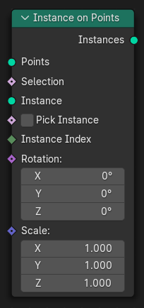
- on_points(points: pynodes.geosocks.Points = None, pick_instance=False, instance_index: pynodes.datasocks.Integer = None, rotation=(0.0, 0.0, 0.0), scale=(1.0, 1.0, 1.0), selection=True)#
The Instance on Points node adds a reference to a geometry to each of the points present in the input geometry. Instances are a fast way to add the same geometry to a scene many times without duplicating the underlying data. The node works on any geometry type with a Point domain, including meshes, point clouds, and curve control points.
In-Place Operation
Path#
Instances > Instance on Points Node
Outputs:#
#0 instances: Geometry = None
- replace_material(old=None, new=None)#
The Replace Material node swaps one material with another. Replacing a material with this node is more efficient than creating a selection of all faces with the old material with the Material Selection Node and then using the Set Material Node.
Path#
Material > Replace Material Node
Outputs:#
#0 geometry: Geometry = None
- set_material(material=None, selection=True)#
The Set Material changes the material assignment in the specified selection, by adjusting the material_index attribute. If the material is already used on the geometry, the existing material index will be reused.
In-Place Operation
Path#
Material > Set Material Node
Outputs:#
#0 geometry: Geometry = None
- set_material_index(material_index=0, selection=True)#
The Set Material Index node sets the material index for a geometry.
In-Place Operation
Path#
Material > Set Material Index Node
Outputs:#
#0 geometry: Geometry = None
- property material_index#
The Material Index node outputs which material in the list of materials of the geometry each element corresponds to. Currently the node supports mesh data, where material_index is a built-in attribute on faces.
Path#
Material > Material Index Node
Outputs:#
#0 material_index: Integer = 0
- static accumulate_float_on_points(value=0.0, group_index=0)#
The Accumulate Field node counts a running total of its input values, in the order defined by the geometry’s indices. The node’s essential operation is just addition, but instead of only outputting the final total, it outputs the current value at every element.
Path#
Utilities > Field > Accumulate Field Node
Outputs:#
#0 leading_float: Float = 0.0#3 trailing_float: Float = 0.0#6 total_float: Float = 0.0
- static accumulate_float_on_edges(value=0.0, group_index=0)#
The Accumulate Field node counts a running total of its input values, in the order defined by the geometry’s indices. The node’s essential operation is just addition, but instead of only outputting the final total, it outputs the current value at every element.
Path#
Utilities > Field > Accumulate Field Node
Outputs:#
#0 leading_float: Float = 0.0#3 trailing_float: Float = 0.0#6 total_float: Float = 0.0
- static accumulate_float_on_faces(value=0.0, group_index=0)#
The Accumulate Field node counts a running total of its input values, in the order defined by the geometry’s indices. The node’s essential operation is just addition, but instead of only outputting the final total, it outputs the current value at every element.
Path#
Utilities > Field > Accumulate Field Node
Outputs:#
#0 leading_float: Float = 0.0#3 trailing_float: Float = 0.0#6 total_float: Float = 0.0
- static accumulate_float_on_corners(value=0.0, group_index=0)#
The Accumulate Field node counts a running total of its input values, in the order defined by the geometry’s indices. The node’s essential operation is just addition, but instead of only outputting the final total, it outputs the current value at every element.
Path#
Utilities > Field > Accumulate Field Node
Outputs:#
#0 leading_float: Float = 0.0#3 trailing_float: Float = 0.0#6 total_float: Float = 0.0
- static accumulate_float_on_curves(value=0.0, group_index=0)#
The Accumulate Field node counts a running total of its input values, in the order defined by the geometry’s indices. The node’s essential operation is just addition, but instead of only outputting the final total, it outputs the current value at every element.
Path#
Utilities > Field > Accumulate Field Node
Outputs:#
#0 leading_float: Float = 0.0#3 trailing_float: Float = 0.0#6 total_float: Float = 0.0
- static accumulate_float_on_instances(value=0.0, group_index=0)#
The Accumulate Field node counts a running total of its input values, in the order defined by the geometry’s indices. The node’s essential operation is just addition, but instead of only outputting the final total, it outputs the current value at every element.
Path#
Utilities > Field > Accumulate Field Node
Outputs:#
#0 leading_float: Float = 0.0#3 trailing_float: Float = 0.0#6 total_float: Float = 0.0
- static accumulate_integer_on_points(value=0, group_index=0)#
The Accumulate Field node counts a running total of its input values, in the order defined by the geometry’s indices. The node’s essential operation is just addition, but instead of only outputting the final total, it outputs the current value at every element.
Path#
Utilities > Field > Accumulate Field Node
Outputs:#
#1 leading_integer: Integer = 0#4 trailing_integer: Integer = 0#7 total_integer: Integer = 0
- static accumulate_integer_on_edges(value=0, group_index=0)#
The Accumulate Field node counts a running total of its input values, in the order defined by the geometry’s indices. The node’s essential operation is just addition, but instead of only outputting the final total, it outputs the current value at every element.
Path#
Utilities > Field > Accumulate Field Node
Outputs:#
#1 leading_integer: Integer = 0#4 trailing_integer: Integer = 0#7 total_integer: Integer = 0
- static accumulate_integer_on_faces(value=0, group_index=0)#
The Accumulate Field node counts a running total of its input values, in the order defined by the geometry’s indices. The node’s essential operation is just addition, but instead of only outputting the final total, it outputs the current value at every element.
Path#
Utilities > Field > Accumulate Field Node
Outputs:#
#1 leading_integer: Integer = 0#4 trailing_integer: Integer = 0#7 total_integer: Integer = 0
- static accumulate_integer_on_corners(value=0, group_index=0)#
The Accumulate Field node counts a running total of its input values, in the order defined by the geometry’s indices. The node’s essential operation is just addition, but instead of only outputting the final total, it outputs the current value at every element.
Path#
Utilities > Field > Accumulate Field Node
Outputs:#
#1 leading_integer: Integer = 0#4 trailing_integer: Integer = 0#7 total_integer: Integer = 0
- static accumulate_integer_on_curves(value=0, group_index=0)#
The Accumulate Field node counts a running total of its input values, in the order defined by the geometry’s indices. The node’s essential operation is just addition, but instead of only outputting the final total, it outputs the current value at every element.
Path#
Utilities > Field > Accumulate Field Node
Outputs:#
#1 leading_integer: Integer = 0#4 trailing_integer: Integer = 0#7 total_integer: Integer = 0
- static accumulate_integer_on_instances(value=0, group_index=0)#
The Accumulate Field node counts a running total of its input values, in the order defined by the geometry’s indices. The node’s essential operation is just addition, but instead of only outputting the final total, it outputs the current value at every element.
Path#
Utilities > Field > Accumulate Field Node
Outputs:#
#1 leading_integer: Integer = 0#4 trailing_integer: Integer = 0#7 total_integer: Integer = 0
- static accumulate_vector_on_points(value=(0.0, 0.0, 0.0), group_index=0)#
The Accumulate Field node counts a running total of its input values, in the order defined by the geometry’s indices. The node’s essential operation is just addition, but instead of only outputting the final total, it outputs the current value at every element.
Path#
Utilities > Field > Accumulate Field Node
Outputs:#
#2 leading_vector: Vector = (0.0, 0.0, 0.0)#5 trailing_vector: Vector = (0.0, 0.0, 0.0)#8 total_vector: Vector = (0.0, 0.0, 0.0)
- static accumulate_vector_on_edges(value=(0.0, 0.0, 0.0), group_index=0)#
The Accumulate Field node counts a running total of its input values, in the order defined by the geometry’s indices. The node’s essential operation is just addition, but instead of only outputting the final total, it outputs the current value at every element.
Path#
Utilities > Field > Accumulate Field Node
Outputs:#
#2 leading_vector: Vector = (0.0, 0.0, 0.0)#5 trailing_vector: Vector = (0.0, 0.0, 0.0)#8 total_vector: Vector = (0.0, 0.0, 0.0)
- static accumulate_vector_on_faces(value=(0.0, 0.0, 0.0), group_index=0)#
The Accumulate Field node counts a running total of its input values, in the order defined by the geometry’s indices. The node’s essential operation is just addition, but instead of only outputting the final total, it outputs the current value at every element.
Path#
Utilities > Field > Accumulate Field Node
Outputs:#
#2 leading_vector: Vector = (0.0, 0.0, 0.0)#5 trailing_vector: Vector = (0.0, 0.0, 0.0)#8 total_vector: Vector = (0.0, 0.0, 0.0)
- static accumulate_vector_on_corners(value=(0.0, 0.0, 0.0), group_index=0)#
The Accumulate Field node counts a running total of its input values, in the order defined by the geometry’s indices. The node’s essential operation is just addition, but instead of only outputting the final total, it outputs the current value at every element.
Path#
Utilities > Field > Accumulate Field Node
Outputs:#
#2 leading_vector: Vector = (0.0, 0.0, 0.0)#5 trailing_vector: Vector = (0.0, 0.0, 0.0)#8 total_vector: Vector = (0.0, 0.0, 0.0)
- static accumulate_vector_on_curves(value=(0.0, 0.0, 0.0), group_index=0)#
The Accumulate Field node counts a running total of its input values, in the order defined by the geometry’s indices. The node’s essential operation is just addition, but instead of only outputting the final total, it outputs the current value at every element.
Path#
Utilities > Field > Accumulate Field Node
Outputs:#
#2 leading_vector: Vector = (0.0, 0.0, 0.0)#5 trailing_vector: Vector = (0.0, 0.0, 0.0)#8 total_vector: Vector = (0.0, 0.0, 0.0)
- static accumulate_vector_on_instances(value=(0.0, 0.0, 0.0), group_index=0)#
The Accumulate Field node counts a running total of its input values, in the order defined by the geometry’s indices. The node’s essential operation is just addition, but instead of only outputting the final total, it outputs the current value at every element.
Path#
Utilities > Field > Accumulate Field Node
Outputs:#
#2 leading_vector: Vector = (0.0, 0.0, 0.0)#5 trailing_vector: Vector = (0.0, 0.0, 0.0)#8 total_vector: Vector = (0.0, 0.0, 0.0)
- static evaluate_float_at_index_on_points(value=0.0, index=0)#
The Evaluate at Index node allows accessing data of other elements in the context geometry. It is similar to the Sample Index Node. The main difference is that this node does not require a geometry input, because the geometry from the field context is used.
Path#
Utilities > Field > Evaluate at Index Node
Outputs:#
#0 value_float: Float = 0.0
- static evaluate_float_at_index_on_edges(value=0.0, index=0)#
The Evaluate at Index node allows accessing data of other elements in the context geometry. It is similar to the Sample Index Node. The main difference is that this node does not require a geometry input, because the geometry from the field context is used.
Path#
Utilities > Field > Evaluate at Index Node
Outputs:#
#0 value_float: Float = 0.0
- static evaluate_float_at_index_on_faces(value=0.0, index=0)#
The Evaluate at Index node allows accessing data of other elements in the context geometry. It is similar to the Sample Index Node. The main difference is that this node does not require a geometry input, because the geometry from the field context is used.
Path#
Utilities > Field > Evaluate at Index Node
Outputs:#
#0 value_float: Float = 0.0
- static evaluate_float_at_index_on_corners(value=0.0, index=0)#
The Evaluate at Index node allows accessing data of other elements in the context geometry. It is similar to the Sample Index Node. The main difference is that this node does not require a geometry input, because the geometry from the field context is used.
Path#
Utilities > Field > Evaluate at Index Node
Outputs:#
#0 value_float: Float = 0.0
- static evaluate_float_at_index_on_curves(value=0.0, index=0)#
The Evaluate at Index node allows accessing data of other elements in the context geometry. It is similar to the Sample Index Node. The main difference is that this node does not require a geometry input, because the geometry from the field context is used.
Path#
Utilities > Field > Evaluate at Index Node
Outputs:#
#0 value_float: Float = 0.0
- static evaluate_float_at_index_on_instances(value=0.0, index=0)#
The Evaluate at Index node allows accessing data of other elements in the context geometry. It is similar to the Sample Index Node. The main difference is that this node does not require a geometry input, because the geometry from the field context is used.
Path#
Utilities > Field > Evaluate at Index Node
Outputs:#
#0 value_float: Float = 0.0
- static evaluate_integer_at_index_on_points(value=0, index=0)#
The Evaluate at Index node allows accessing data of other elements in the context geometry. It is similar to the Sample Index Node. The main difference is that this node does not require a geometry input, because the geometry from the field context is used.
Path#
Utilities > Field > Evaluate at Index Node
Outputs:#
#1 value_int: Integer = 0
- static evaluate_integer_at_index_on_edges(value=0, index=0)#
The Evaluate at Index node allows accessing data of other elements in the context geometry. It is similar to the Sample Index Node. The main difference is that this node does not require a geometry input, because the geometry from the field context is used.
Path#
Utilities > Field > Evaluate at Index Node
Outputs:#
#1 value_int: Integer = 0
- static evaluate_integer_at_index_on_faces(value=0, index=0)#
The Evaluate at Index node allows accessing data of other elements in the context geometry. It is similar to the Sample Index Node. The main difference is that this node does not require a geometry input, because the geometry from the field context is used.
Path#
Utilities > Field > Evaluate at Index Node
Outputs:#
#1 value_int: Integer = 0
- static evaluate_integer_at_index_on_corners(value=0, index=0)#
The Evaluate at Index node allows accessing data of other elements in the context geometry. It is similar to the Sample Index Node. The main difference is that this node does not require a geometry input, because the geometry from the field context is used.
Path#
Utilities > Field > Evaluate at Index Node
Outputs:#
#1 value_int: Integer = 0
- static evaluate_integer_at_index_on_curves(value=0, index=0)#
The Evaluate at Index node allows accessing data of other elements in the context geometry. It is similar to the Sample Index Node. The main difference is that this node does not require a geometry input, because the geometry from the field context is used.
Path#
Utilities > Field > Evaluate at Index Node
Outputs:#
#1 value_int: Integer = 0
- static evaluate_integer_at_index_on_instances(value=0, index=0)#
The Evaluate at Index node allows accessing data of other elements in the context geometry. It is similar to the Sample Index Node. The main difference is that this node does not require a geometry input, because the geometry from the field context is used.
Path#
Utilities > Field > Evaluate at Index Node
Outputs:#
#1 value_int: Integer = 0
- static evaluate_vector_at_index_on_points(value=(0.0, 0.0, 0.0), index=0)#
The Evaluate at Index node allows accessing data of other elements in the context geometry. It is similar to the Sample Index Node. The main difference is that this node does not require a geometry input, because the geometry from the field context is used.
Path#
Utilities > Field > Evaluate at Index Node
Outputs:#
#2 value_vector: Vector = (0.0, 0.0, 0.0)
- static evaluate_vector_at_index_on_edges(value=(0.0, 0.0, 0.0), index=0)#
The Evaluate at Index node allows accessing data of other elements in the context geometry. It is similar to the Sample Index Node. The main difference is that this node does not require a geometry input, because the geometry from the field context is used.
Path#
Utilities > Field > Evaluate at Index Node
Outputs:#
#2 value_vector: Vector = (0.0, 0.0, 0.0)
- static evaluate_vector_at_index_on_faces(value=(0.0, 0.0, 0.0), index=0)#
The Evaluate at Index node allows accessing data of other elements in the context geometry. It is similar to the Sample Index Node. The main difference is that this node does not require a geometry input, because the geometry from the field context is used.
Path#
Utilities > Field > Evaluate at Index Node
Outputs:#
#2 value_vector: Vector = (0.0, 0.0, 0.0)
- static evaluate_vector_at_index_on_corners(value=(0.0, 0.0, 0.0), index=0)#
The Evaluate at Index node allows accessing data of other elements in the context geometry. It is similar to the Sample Index Node. The main difference is that this node does not require a geometry input, because the geometry from the field context is used.
Path#
Utilities > Field > Evaluate at Index Node
Outputs:#
#2 value_vector: Vector = (0.0, 0.0, 0.0)
- static evaluate_vector_at_index_on_curves(value=(0.0, 0.0, 0.0), index=0)#
The Evaluate at Index node allows accessing data of other elements in the context geometry. It is similar to the Sample Index Node. The main difference is that this node does not require a geometry input, because the geometry from the field context is used.
Path#
Utilities > Field > Evaluate at Index Node
Outputs:#
#2 value_vector: Vector = (0.0, 0.0, 0.0)
- static evaluate_vector_at_index_on_instances(value=(0.0, 0.0, 0.0), index=0)#
The Evaluate at Index node allows accessing data of other elements in the context geometry. It is similar to the Sample Index Node. The main difference is that this node does not require a geometry input, because the geometry from the field context is used.
Path#
Utilities > Field > Evaluate at Index Node
Outputs:#
#2 value_vector: Vector = (0.0, 0.0, 0.0)
- static evaluate_color_at_index_on_points(value=(0.0, 0.0, 0.0, 0.0), index=0)#
The Evaluate at Index node allows accessing data of other elements in the context geometry. It is similar to the Sample Index Node. The main difference is that this node does not require a geometry input, because the geometry from the field context is used.
Path#
Utilities > Field > Evaluate at Index Node
Outputs:#
#3 value_color: Color = (0.0, 0.0, 0.0, 0.0)
- static evaluate_color_at_index_on_edges(value=(0.0, 0.0, 0.0, 0.0), index=0)#
The Evaluate at Index node allows accessing data of other elements in the context geometry. It is similar to the Sample Index Node. The main difference is that this node does not require a geometry input, because the geometry from the field context is used.
Path#
Utilities > Field > Evaluate at Index Node
Outputs:#
#3 value_color: Color = (0.0, 0.0, 0.0, 0.0)
- static evaluate_color_at_index_on_faces(value=(0.0, 0.0, 0.0, 0.0), index=0)#
The Evaluate at Index node allows accessing data of other elements in the context geometry. It is similar to the Sample Index Node. The main difference is that this node does not require a geometry input, because the geometry from the field context is used.
Path#
Utilities > Field > Evaluate at Index Node
Outputs:#
#3 value_color: Color = (0.0, 0.0, 0.0, 0.0)
- static evaluate_color_at_index_on_corners(value=(0.0, 0.0, 0.0, 0.0), index=0)#
The Evaluate at Index node allows accessing data of other elements in the context geometry. It is similar to the Sample Index Node. The main difference is that this node does not require a geometry input, because the geometry from the field context is used.
Path#
Utilities > Field > Evaluate at Index Node
Outputs:#
#3 value_color: Color = (0.0, 0.0, 0.0, 0.0)
- static evaluate_color_at_index_on_curves(value=(0.0, 0.0, 0.0, 0.0), index=0)#
The Evaluate at Index node allows accessing data of other elements in the context geometry. It is similar to the Sample Index Node. The main difference is that this node does not require a geometry input, because the geometry from the field context is used.
Path#
Utilities > Field > Evaluate at Index Node
Outputs:#
#3 value_color: Color = (0.0, 0.0, 0.0, 0.0)
- static evaluate_color_at_index_on_instances(value=(0.0, 0.0, 0.0, 0.0), index=0)#
The Evaluate at Index node allows accessing data of other elements in the context geometry. It is similar to the Sample Index Node. The main difference is that this node does not require a geometry input, because the geometry from the field context is used.
Path#
Utilities > Field > Evaluate at Index Node
Outputs:#
#3 value_color: Color = (0.0, 0.0, 0.0, 0.0)
- static evaluate_boolean_at_index_on_points(value=False, index=0)#
The Evaluate at Index node allows accessing data of other elements in the context geometry. It is similar to the Sample Index Node. The main difference is that this node does not require a geometry input, because the geometry from the field context is used.
Path#
Utilities > Field > Evaluate at Index Node
Outputs:#
#4 value_bool: Boolean = False
- static evaluate_boolean_at_index_on_edges(value=False, index=0)#
The Evaluate at Index node allows accessing data of other elements in the context geometry. It is similar to the Sample Index Node. The main difference is that this node does not require a geometry input, because the geometry from the field context is used.
Path#
Utilities > Field > Evaluate at Index Node
Outputs:#
#4 value_bool: Boolean = False
- static evaluate_boolean_at_index_on_faces(value=False, index=0)#
The Evaluate at Index node allows accessing data of other elements in the context geometry. It is similar to the Sample Index Node. The main difference is that this node does not require a geometry input, because the geometry from the field context is used.
Path#
Utilities > Field > Evaluate at Index Node
Outputs:#
#4 value_bool: Boolean = False
- static evaluate_boolean_at_index_on_corners(value=False, index=0)#
The Evaluate at Index node allows accessing data of other elements in the context geometry. It is similar to the Sample Index Node. The main difference is that this node does not require a geometry input, because the geometry from the field context is used.
Path#
Utilities > Field > Evaluate at Index Node
Outputs:#
#4 value_bool: Boolean = False
- static evaluate_boolean_at_index_on_curves(value=False, index=0)#
The Evaluate at Index node allows accessing data of other elements in the context geometry. It is similar to the Sample Index Node. The main difference is that this node does not require a geometry input, because the geometry from the field context is used.
Path#
Utilities > Field > Evaluate at Index Node
Outputs:#
#4 value_bool: Boolean = False
- static evaluate_boolean_at_index_on_instances(value=False, index=0)#
The Evaluate at Index node allows accessing data of other elements in the context geometry. It is similar to the Sample Index Node. The main difference is that this node does not require a geometry input, because the geometry from the field context is used.
Path#
Utilities > Field > Evaluate at Index Node
Outputs:#
#4 value_bool: Boolean = False
- static evaluate_float_on_points(value=0.0)#
The Evaluate on Domain allows evaluating a field for a different attribute domain than the domain from the field context. For example, the face index could be used instead of the face corner index, when setting the values of a UV Map
Path#
Utilities > Field > Evaluate on Domain Node
Outputs:#
#0 value_float: Float = 0.0
- static evaluate_float_on_edges(value=0.0)#
The Evaluate on Domain allows evaluating a field for a different attribute domain than the domain from the field context. For example, the face index could be used instead of the face corner index, when setting the values of a UV Map
Path#
Utilities > Field > Evaluate on Domain Node
Outputs:#
#0 value_float: Float = 0.0
- static evaluate_float_on_faces(value=0.0)#
The Evaluate on Domain allows evaluating a field for a different attribute domain than the domain from the field context. For example, the face index could be used instead of the face corner index, when setting the values of a UV Map
Path#
Utilities > Field > Evaluate on Domain Node
Outputs:#
#0 value_float: Float = 0.0
- static evaluate_float_on_corners(value=0.0)#
The Evaluate on Domain allows evaluating a field for a different attribute domain than the domain from the field context. For example, the face index could be used instead of the face corner index, when setting the values of a UV Map
Path#
Utilities > Field > Evaluate on Domain Node
Outputs:#
#0 value_float: Float = 0.0
- static evaluate_float_on_curves(value=0.0)#
The Evaluate on Domain allows evaluating a field for a different attribute domain than the domain from the field context. For example, the face index could be used instead of the face corner index, when setting the values of a UV Map
Path#
Utilities > Field > Evaluate on Domain Node
Outputs:#
#0 value_float: Float = 0.0
- static evaluate_float_on_instances(value=0.0)#
The Evaluate on Domain allows evaluating a field for a different attribute domain than the domain from the field context. For example, the face index could be used instead of the face corner index, when setting the values of a UV Map
Path#
Utilities > Field > Evaluate on Domain Node
Outputs:#
#0 value_float: Float = 0.0
- static evaluate_integer_on_points(value=0)#
The Evaluate on Domain allows evaluating a field for a different attribute domain than the domain from the field context. For example, the face index could be used instead of the face corner index, when setting the values of a UV Map
Path#
Utilities > Field > Evaluate on Domain Node
Outputs:#
#1 value_int: Integer = 0
- static evaluate_integer_on_edges(value=0)#
The Evaluate on Domain allows evaluating a field for a different attribute domain than the domain from the field context. For example, the face index could be used instead of the face corner index, when setting the values of a UV Map
Path#
Utilities > Field > Evaluate on Domain Node
Outputs:#
#1 value_int: Integer = 0
- static evaluate_integer_on_faces(value=0)#
The Evaluate on Domain allows evaluating a field for a different attribute domain than the domain from the field context. For example, the face index could be used instead of the face corner index, when setting the values of a UV Map
Path#
Utilities > Field > Evaluate on Domain Node
Outputs:#
#1 value_int: Integer = 0
- static evaluate_integer_on_corners(value=0)#
The Evaluate on Domain allows evaluating a field for a different attribute domain than the domain from the field context. For example, the face index could be used instead of the face corner index, when setting the values of a UV Map
Path#
Utilities > Field > Evaluate on Domain Node
Outputs:#
#1 value_int: Integer = 0
- static evaluate_integer_on_curves(value=0)#
The Evaluate on Domain allows evaluating a field for a different attribute domain than the domain from the field context. For example, the face index could be used instead of the face corner index, when setting the values of a UV Map
Path#
Utilities > Field > Evaluate on Domain Node
Outputs:#
#1 value_int: Integer = 0
- static evaluate_integer_on_instances(value=0)#
The Evaluate on Domain allows evaluating a field for a different attribute domain than the domain from the field context. For example, the face index could be used instead of the face corner index, when setting the values of a UV Map
Path#
Utilities > Field > Evaluate on Domain Node
Outputs:#
#1 value_int: Integer = 0
- static evaluate_vector_on_points(value=(0.0, 0.0, 0.0))#
The Evaluate on Domain allows evaluating a field for a different attribute domain than the domain from the field context. For example, the face index could be used instead of the face corner index, when setting the values of a UV Map
Path#
Utilities > Field > Evaluate on Domain Node
Outputs:#
#2 value_vector: Vector = (0.0, 0.0, 0.0)
- static evaluate_vector_on_edges(value=(0.0, 0.0, 0.0))#
The Evaluate on Domain allows evaluating a field for a different attribute domain than the domain from the field context. For example, the face index could be used instead of the face corner index, when setting the values of a UV Map
Path#
Utilities > Field > Evaluate on Domain Node
Outputs:#
#2 value_vector: Vector = (0.0, 0.0, 0.0)
- static evaluate_vector_on_faces(value=(0.0, 0.0, 0.0))#
The Evaluate on Domain allows evaluating a field for a different attribute domain than the domain from the field context. For example, the face index could be used instead of the face corner index, when setting the values of a UV Map
Path#
Utilities > Field > Evaluate on Domain Node
Outputs:#
#2 value_vector: Vector = (0.0, 0.0, 0.0)
- static evaluate_vector_on_corners(value=(0.0, 0.0, 0.0))#
The Evaluate on Domain allows evaluating a field for a different attribute domain than the domain from the field context. For example, the face index could be used instead of the face corner index, when setting the values of a UV Map
Path#
Utilities > Field > Evaluate on Domain Node
Outputs:#
#2 value_vector: Vector = (0.0, 0.0, 0.0)
- static evaluate_vector_on_curves(value=(0.0, 0.0, 0.0))#
The Evaluate on Domain allows evaluating a field for a different attribute domain than the domain from the field context. For example, the face index could be used instead of the face corner index, when setting the values of a UV Map
Path#
Utilities > Field > Evaluate on Domain Node
Outputs:#
#2 value_vector: Vector = (0.0, 0.0, 0.0)
- static evaluate_vector_on_instances(value=(0.0, 0.0, 0.0))#
The Evaluate on Domain allows evaluating a field for a different attribute domain than the domain from the field context. For example, the face index could be used instead of the face corner index, when setting the values of a UV Map
Path#
Utilities > Field > Evaluate on Domain Node
Outputs:#
#2 value_vector: Vector = (0.0, 0.0, 0.0)
- static evaluate_color_on_points(value=(0.0, 0.0, 0.0, 0.0))#
The Evaluate on Domain allows evaluating a field for a different attribute domain than the domain from the field context. For example, the face index could be used instead of the face corner index, when setting the values of a UV Map
Path#
Utilities > Field > Evaluate on Domain Node
Outputs:#
#3 value_color: Color = (0.0, 0.0, 0.0, 0.0)
- static evaluate_color_on_edges(value=(0.0, 0.0, 0.0, 0.0))#
The Evaluate on Domain allows evaluating a field for a different attribute domain than the domain from the field context. For example, the face index could be used instead of the face corner index, when setting the values of a UV Map
Path#
Utilities > Field > Evaluate on Domain Node
Outputs:#
#3 value_color: Color = (0.0, 0.0, 0.0, 0.0)
- static evaluate_color_on_faces(value=(0.0, 0.0, 0.0, 0.0))#
The Evaluate on Domain allows evaluating a field for a different attribute domain than the domain from the field context. For example, the face index could be used instead of the face corner index, when setting the values of a UV Map
Path#
Utilities > Field > Evaluate on Domain Node
Outputs:#
#3 value_color: Color = (0.0, 0.0, 0.0, 0.0)
- static evaluate_color_on_corners(value=(0.0, 0.0, 0.0, 0.0))#
The Evaluate on Domain allows evaluating a field for a different attribute domain than the domain from the field context. For example, the face index could be used instead of the face corner index, when setting the values of a UV Map
Path#
Utilities > Field > Evaluate on Domain Node
Outputs:#
#3 value_color: Color = (0.0, 0.0, 0.0, 0.0)
- static evaluate_color_on_curves(value=(0.0, 0.0, 0.0, 0.0))#
The Evaluate on Domain allows evaluating a field for a different attribute domain than the domain from the field context. For example, the face index could be used instead of the face corner index, when setting the values of a UV Map
Path#
Utilities > Field > Evaluate on Domain Node
Outputs:#
#3 value_color: Color = (0.0, 0.0, 0.0, 0.0)
- static evaluate_color_on_instances(value=(0.0, 0.0, 0.0, 0.0))#
The Evaluate on Domain allows evaluating a field for a different attribute domain than the domain from the field context. For example, the face index could be used instead of the face corner index, when setting the values of a UV Map
Path#
Utilities > Field > Evaluate on Domain Node
Outputs:#
#3 value_color: Color = (0.0, 0.0, 0.0, 0.0)
- static evaluate_boolean_on_points(value=False)#
The Evaluate on Domain allows evaluating a field for a different attribute domain than the domain from the field context. For example, the face index could be used instead of the face corner index, when setting the values of a UV Map
Path#
Utilities > Field > Evaluate on Domain Node
Outputs:#
#4 value_bool: Boolean = False
- static evaluate_boolean_on_edges(value=False)#
The Evaluate on Domain allows evaluating a field for a different attribute domain than the domain from the field context. For example, the face index could be used instead of the face corner index, when setting the values of a UV Map
Path#
Utilities > Field > Evaluate on Domain Node
Outputs:#
#4 value_bool: Boolean = False
- static evaluate_boolean_on_faces(value=False)#
The Evaluate on Domain allows evaluating a field for a different attribute domain than the domain from the field context. For example, the face index could be used instead of the face corner index, when setting the values of a UV Map
Path#
Utilities > Field > Evaluate on Domain Node
Outputs:#
#4 value_bool: Boolean = False
- static evaluate_boolean_on_corners(value=False)#
The Evaluate on Domain allows evaluating a field for a different attribute domain than the domain from the field context. For example, the face index could be used instead of the face corner index, when setting the values of a UV Map
Path#
Utilities > Field > Evaluate on Domain Node
Outputs:#
#4 value_bool: Boolean = False
- static evaluate_boolean_on_curves(value=False)#
The Evaluate on Domain allows evaluating a field for a different attribute domain than the domain from the field context. For example, the face index could be used instead of the face corner index, when setting the values of a UV Map
Path#
Utilities > Field > Evaluate on Domain Node
Outputs:#
#4 value_bool: Boolean = False
- static evaluate_boolean_on_instances(value=False)#
The Evaluate on Domain allows evaluating a field for a different attribute domain than the domain from the field context. For example, the face index could be used instead of the face corner index, when setting the values of a UV Map
Path#
Utilities > Field > Evaluate on Domain Node
Outputs:#
#4 value_bool: Boolean = False
- realize_instances(legacy_behavior=False)#
The Realize Instances node makes any instances (efficient duplicates of the same geometry) into real geometry data. This makes it possible to affect each instance individually, whereas without this node, the exact same changes are applied to every instance of the same geometry. However, performance can become much worse when the input contains many instances of complex geometry, which is a fundamental limitation when procedurally processing geometry.
In-Place Operation
Path#
Instances > Realize Instances Node
Outputs:#
#0 geometry: Geometry = None
- index_of_nearest(position=None, group_id=0)#
The Index of Nearest node is a way to find other close elements in the same geometry. If needed you can use Group ID to determine the group of neighbors to be analyzed together.This is an alternative to the Sample Nearest Node node. The main difference is that this node does not require a geometry input, because the geometry from the field context is used.
New in Blender 3.6.0
Path#
Geometry > Sample
Outputs:#
#0 index: Integer = 0#1 has_neighbor: Boolean = False
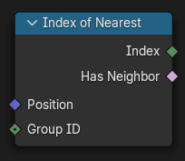
- class pynodes.geosocks.Curve(bsocket: bpy.types.NodeSocket)#
Bases:
pynodes.geosocks.GeometryA Curve data socket
Initialization
- property domain_size#
The Domain Size outputs the size of an attribute domain on the selected geometry type, for example, the number of edges in a mesh, or the number of points in a point cloud.
Path#
Attribute > Domain Size Node
Outputs:#
#0 point_count: Integer = 0#4 spline_count: Integer = 0
- static handle_positions(relative=False)#
The Curve Handle Position node outputs the position of each of a Bézier spline’s handles. If the curve does not contain Bézier splines, the node will output zero.
Path#
Curve > Read > Curve Handle Position Node
Outputs:#
#0 left: Vector = (0.0, 0.0, 0.0)#1 right: Vector = (0.0, 0.0, 0.0)
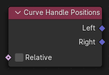
- property curve_length#
The Curve Length node outputs the length of all splines added together.
Path#
Curve > Read > Curve Length Node
Outputs:#
#0 length: Float = 0.0
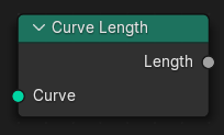
- property spline_length#
The Spline Length node outputs the total length of each spline, as a distance, or a number of points. This is different than the Curve Length node, which adds up the total length for all of the curve’s splines.
Path#
Curve > Read > Spline Length Node
Outputs:#
#0 length: Float = 0.0#1 point_count: Integer = 0
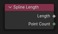
- property tangent#
The Curve Tangent node outputs the direction that a curve points in at each control point, depending on the direction of the curve (which can be controlled with the Reverse Curve Node). The output values are normalized vectors.
Path#
Curve > Read > Curve Tangent Node
Outputs:#
#0 tangent: Vector = (0.0, 0.0, 0.0)
- property tilt#
The Curve Tilt node outputs the angle used to turn the curve normal around the direction of the curve tangent in its evaluated points. Keep in mind that the output is per control point, just like the values that can be controlled in curve Edit Mode. For NURBS and Bézier splines, the values will be interpolated to the final evaluated points.
Path#
Curve > Read > Curve Tilt Node
Outputs:#
#0 tilt: Float = 0.0
- static endpoint_selection(start_size=1, end_size=1)#
The Endpoint Selection node provides a selection for an arbitrary number of endpoints in each spline in a curve.
Path#
Curve > Read > Endpoint Selection Node
Outputs:#
#0 selection: Boolean = False
- static handle_type_selection(handle_type='AUTO', mode: set = {'LEFT', 'RIGHT'})#
Creates a selection based on the handle types of the control points.
Path#
Curve > Read > Handle Type Selection Node
Properties#
handle_type:AUTO,FREE,VECTOR,ALIGN
Outputs:#
#0 selection: Boolean = False
- property is_cyclic#
The Is Spline Cyclic controls whether each of the curve splines start and endpoints form a connection. Its output corresponds to the built-in cyclic attribute on the curve spline domain.
Path#
Curve > Read > Is Spline Cyclic Node
Outputs:#
#0 cyclic: Boolean = False
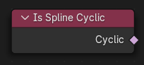
- property parameter#
The Spline Parameter node outputs how far along each spline a control point is. The Factor output is different from dividing the index by the total number of control points, because the control points might not be equally spaced along the curve.
Path#
Curve > Read > Spline Parameter Node
Outputs:#
#0 factor: Float = 0.0#1 length: Float = 0.0#2 index: Integer = 0
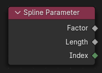
- property resolution#
The Spline Resolution outputs the number of evaluated curve points that will be generated for every control point on the spline. This node works for NURBS and Bézier splines, for poly splines, there is a one-to-one correspondence between original points and evaluated points, so the resolution value will be 1.
Path#
Curve > Read > Spline Resolution Node
Outputs:#
#0 resolution: Integer = 0
- sample_curve(data_type='FLOAT', mode='FACTOR', use_all_curves=False, value_float=0.0, value_int=0, value_vector=(0.0, 0.0, 0.0), value_color=(0.0, 0.0, 0.0, 0.0), value_bool=False, factor=0.0, length=0.0, curve_index=0)#
The Sample Curve calculates a point on a curve at a certain distance from the start of the curve, specified by the length or factor inputs. It also outputs data retrieved from that position on the curve. The sampled values are linearly interpolated from the values at the evaluated curve points at each side of the sampled point.
Path#
Curve > Sample > Sample Curve Node
Properties#
data_type:FLOAT,INT,FLOAT_VECTOR,FLOAT_COLOR,BOOLEANmode:FACTOR,LENGTH
Outputs:#
#0 value_float: Float = 0.0#1 value_int: Integer = 0#2 value_vector: Vector = (0.0, 0.0, 0.0)#3 value_color: Color = (0.0, 0.0, 0.0, 0.0)#4 value_bool: Boolean = False#5 position: Vector = (0.0, 0.0, 0.0)#6 tangent: Vector = (0.0, 0.0, 0.0)#7 normal: Vector = (0.0, 0.0, 0.0)
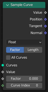
- sample_float(mode='FACTOR', use_all_curves=False, value_float=0.0, factor=0.0, length=0.0, curve_index=0)#
The Sample Curve calculates a point on a curve at a certain distance from the start of the curve, specified by the length or factor inputs. It also outputs data retrieved from that position on the curve. The sampled values are linearly interpolated from the values at the evaluated curve points at each side of the sampled point.
Path#
Curve > Sample > Sample Curve Node
Properties#
mode:FACTOR,LENGTH
Outputs:#
#0 value_float: Float = 0.0#5 position: Vector = (0.0, 0.0, 0.0)#6 tangent: Vector = (0.0, 0.0, 0.0)#7 normal: Vector = (0.0, 0.0, 0.0)
- sample_integer(mode='FACTOR', use_all_curves=False, value_int=0, factor=0.0, length=0.0, curve_index=0)#
The Sample Curve calculates a point on a curve at a certain distance from the start of the curve, specified by the length or factor inputs. It also outputs data retrieved from that position on the curve. The sampled values are linearly interpolated from the values at the evaluated curve points at each side of the sampled point.
Path#
Curve > Sample > Sample Curve Node
Properties#
mode:FACTOR,LENGTH
Outputs:#
#1 value_int: Integer = 0#5 position: Vector = (0.0, 0.0, 0.0)#6 tangent: Vector = (0.0, 0.0, 0.0)#7 normal: Vector = (0.0, 0.0, 0.0)
- sample_vector(mode='FACTOR', use_all_curves=False, value_vector=(0.0, 0.0, 0.0), factor=0.0, length=0.0, curve_index=0)#
The Sample Curve calculates a point on a curve at a certain distance from the start of the curve, specified by the length or factor inputs. It also outputs data retrieved from that position on the curve. The sampled values are linearly interpolated from the values at the evaluated curve points at each side of the sampled point.
Path#
Curve > Sample > Sample Curve Node
Properties#
mode:FACTOR,LENGTH
Outputs:#
#2 value_vector: Vector = (0.0, 0.0, 0.0)#5 position: Vector = (0.0, 0.0, 0.0)#6 tangent: Vector = (0.0, 0.0, 0.0)#7 normal: Vector = (0.0, 0.0, 0.0)
- sample_color(mode='FACTOR', use_all_curves=False, value_color=(0.0, 0.0, 0.0, 0.0), factor=0.0, length=0.0, curve_index=0)#
The Sample Curve calculates a point on a curve at a certain distance from the start of the curve, specified by the length or factor inputs. It also outputs data retrieved from that position on the curve. The sampled values are linearly interpolated from the values at the evaluated curve points at each side of the sampled point.
Path#
Curve > Sample > Sample Curve Node
Properties#
mode:FACTOR,LENGTH
Outputs:#
#3 value_color: Color = (0.0, 0.0, 0.0, 0.0)#5 position: Vector = (0.0, 0.0, 0.0)#6 tangent: Vector = (0.0, 0.0, 0.0)#7 normal: Vector = (0.0, 0.0, 0.0)
- sample_boolean(mode='FACTOR', use_all_curves=False, value_bool=False, factor=0.0, length=0.0, curve_index=0)#
The Sample Curve calculates a point on a curve at a certain distance from the start of the curve, specified by the length or factor inputs. It also outputs data retrieved from that position on the curve. The sampled values are linearly interpolated from the values at the evaluated curve points at each side of the sampled point.
Path#
Curve > Sample > Sample Curve Node
Properties#
mode:FACTOR,LENGTH
Outputs:#
#4 value_bool: Boolean = False#5 position: Vector = (0.0, 0.0, 0.0)#6 tangent: Vector = (0.0, 0.0, 0.0)#7 normal: Vector = (0.0, 0.0, 0.0)
- set_normal(mode='MINIMUM_TWIST', selection=True)#
The Set Curve Normal controls the method used to calculate curve normals for every curve.
In-Place Operation
Path#
Curve > Write > Set Curve Normal Node
Properties#
mode:MINIMUM_TWIST,Z_UP
Outputs:#
#0 curve: Geometry = None
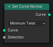
- set_radius(radius=0.005, selection=True)#
The Set Curve Radius controls the radius of the curve, used for operations like the size of the profile in the Curve to Mesh node. The value is set for every control point, and is then interpolated to each evaluated point in between the control points.
In-Place Operation
Path#
Curve > Write > Set Curve Radius Node
Outputs:#
#0 curve: Geometry = None
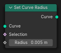
- set_tilt(tilt=math.radians(0.0), selection=True)#
The Set Curve Tilt controls the tilt angle at each curve control point. That angle rotates normal vector which is generated at each point when evaluating the curve. The normal then can be retrieved with the Normal Node.
In-Place Operation
Path#
Curve > Write > Set Curve Tilt Node
Outputs:#
#0 curve: Geometry = None
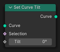
- set_handle_positions(mode='LEFT', position: pynodes.datasocks.Vector = None, offset=(0.0, 0.0, 0.0), selection=True)#
The Set Handle Positions node sets the positions for the handles of Bézier curves. They can be used to alter the generated shape of the curve. The input node for this data is the Curve Handle Position Node. See the Bézier curves page for more details.
In-Place Operation
Path#
Curve > Write > Set Handle Positions Node
Properties#
mode:LEFT,RIGHT
Outputs:#
#0 curve: Geometry = None
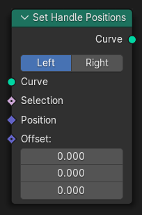
- set_handle_type(handle_type='AUTO', mode: set = {'LEFT', 'RIGHT'}, selection=True)#
Sets the handle type for the points on the Bézier curve that are in the selection.
In-Place Operation
Path#
Curve > Write > Set Handle Type Node
Properties#
handle_type:AUTO,FREE,VECTOR,ALIGN
Outputs:#
#0 curve: Geometry = None
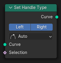
- set_cyclic(cyclic=False, selection=True)#
The Set Spline Cyclic controls whether each spline will loop back on itself. Each spline has the same number of control points whether or not it is set as cyclic. But when displaying in the viewport or for operations with other nodes, a connection will be made between the first and last control points.
In-Place Operation
Path#
Curve > Write > Set Spline Cyclic Node
Outputs:#
#0 geometry: Geometry = None
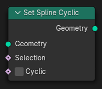
- set_resolution(resolution=12, selection=True)#
The Set Spline Resolution node sets the value for how many evaluated points should be generated on the curve for every control point. It only has an effect on NURBS and Bézier splines. The evaluated points are displayed in the viewport, used in the Curve to Mesh Node node, and optionally used in the Resample Curve Node.
In-Place Operation
Path#
Curve > Write > Set Spline Resolution Node
Outputs:#
#0 geometry: Geometry = None
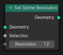
- set_spline_type(spline_type='POLY', selection=True)#
Sets the spline type for the splines in the curve component that are in the selection.
In-Place Operation
Path#
Curve > Write > Set Spline Type Node
Properties#
spline_type:POLY,CATMULL_ROM,BEZIER,NURBS
Outputs:#
#0 curve: Geometry = None
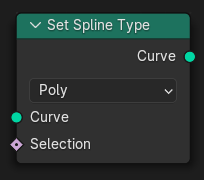
- set_spline_type_poly(selection=True)#
Sets the spline type for the splines in the curve component that are in the selection.
In-Place Operation
Path#
Curve > Write > Set Spline Type Node
Properties#
spline_type:POLY,CATMULL_ROM,BEZIER,NURBS
Outputs:#
#0 curve: Geometry = None
- set_spline_type_catmull_rom(selection=True)#
Sets the spline type for the splines in the curve component that are in the selection.
In-Place Operation
Path#
Curve > Write > Set Spline Type Node
Properties#
spline_type:POLY,CATMULL_ROM,BEZIER,NURBS
Outputs:#
#0 curve: Geometry = None
- set_spline_type_bezier(selection=True)#
Sets the spline type for the splines in the curve component that are in the selection.
In-Place Operation
Path#
Curve > Write > Set Spline Type Node
Properties#
spline_type:POLY,CATMULL_ROM,BEZIER,NURBS
Outputs:#
#0 curve: Geometry = None
- set_spline_type_nurbs(selection=True)#
Sets the spline type for the splines in the curve component that are in the selection.
In-Place Operation
Path#
Curve > Write > Set Spline Type Node
Properties#
spline_type:POLY,CATMULL_ROM,BEZIER,NURBS
Outputs:#
#0 curve: Geometry = None
- to_mesh(profile: pynodes.geosocks.Curve = None, fill_caps=False)#
The Curve to Mesh node converts all splines of a curve to a mesh. Optionally, a profile curve can be provided to give the curve a custom shape.
Path#
Curve > Operations > Curve to Mesh Node
Outputs:#
#0 mesh: Geometry = None
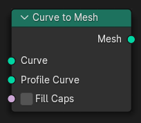
- to_points(mode='COUNT', count=10, length=0.1)#
The Curve to Points node generates a point cloud from a curve.
Path#
Curve > Operations > Curve to Points Node
Properties#
mode:COUNT,EVALUATED,LENGTH
Outputs:#
#0 points: Geometry = None#1 tangent: Vector = (0.0, 0.0, 0.0)#2 normal: Vector = (0.0, 0.0, 0.0)#3 rotation: Vector = (0.0, 0.0, 0.0)
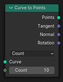
- to_points_with_count(count=10)#
The Curve to Points node generates a point cloud from a curve.
Path#
Curve > Operations > Curve to Points Node
Properties#
mode:COUNT,EVALUATED,LENGTH
Outputs:#
#0 points: Geometry = None#1 tangent: Vector = (0.0, 0.0, 0.0)#2 normal: Vector = (0.0, 0.0, 0.0)#3 rotation: Vector = (0.0, 0.0, 0.0)
- to_points_with_length(length=0.1)#
The Curve to Points node generates a point cloud from a curve.
Path#
Curve > Operations > Curve to Points Node
Properties#
mode:COUNT,EVALUATED,LENGTH
Outputs:#
#0 points: Geometry = None#1 tangent: Vector = (0.0, 0.0, 0.0)#2 normal: Vector = (0.0, 0.0, 0.0)#3 rotation: Vector = (0.0, 0.0, 0.0)
- to_points_evaluated()#
The Curve to Points node generates a point cloud from a curve.
Path#
Curve > Operations > Curve to Points Node
Properties#
mode:COUNT,EVALUATED,LENGTH
Outputs:#
#0 points: Geometry = None#1 tangent: Vector = (0.0, 0.0, 0.0)#2 normal: Vector = (0.0, 0.0, 0.0)#3 rotation: Vector = (0.0, 0.0, 0.0)
- property points_evaluated#
The Curve to Points node generates a point cloud from a curve.
Path#
Curve > Operations > Curve to Points Node
Properties#
mode:COUNT,EVALUATED,LENGTH
Outputs:#
#0 points: Geometry = None#1 tangent: Vector = (0.0, 0.0, 0.0)#2 normal: Vector = (0.0, 0.0, 0.0)#3 rotation: Vector = (0.0, 0.0, 0.0)
- deform_on_surface()#
The Deform Curves on Surface node translates and rotates each curve based on the difference in its root position. The root position is defined by UV coordinates stored on each curve and the UV Map selected for the purpose in the Curves surface settings.
Path#
Curve > Operations > Deform Curves on Surface Node
Outputs:#
#0 curves: Geometry = None
- fill_curve(mode='TRIANGLES')#
The Fill Curve node generates a mesh using the constrained Delaunay triangulation algorithm with the curves as boundaries. The mesh is only generated flat with a local Z of 0.
Path#
Curve > Operations > Fill Curve Node
Properties#
mode:TRIANGLES,NGONS
Outputs:#
#0 mesh: Geometry = None
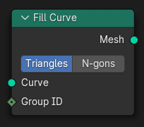
- property filled_mesh#
The Fill Curve node generates a mesh using the constrained Delaunay triangulation algorithm with the curves as boundaries. The mesh is only generated flat with a local Z of 0.
Path#
Curve > Operations > Fill Curve Node
Outputs:#
#0 mesh: Geometry = None
- property filled_ngons#
The Fill Curve node generates a mesh using the constrained Delaunay triangulation algorithm with the curves as boundaries. The mesh is only generated flat with a local Z of 0.
Path#
Curve > Operations > Fill Curve Node
Outputs:#
#0 mesh: Geometry = None
- fillet_curve(mode='BEZIER', count=1, radius=0.25, limit_radius=False)#
The Fillet Curve rounds corners on curve control points, similar to the effect of the Bevel Modifier on a 2D mesh. However, a key difference is that the rounded portions created by the Fillet Curve node are always portions of a circle.
Path#
Curve > Operations > Fillet Curve Node
Properties#
mode:BEZIER,POLY
Outputs:#
#0 curve: Geometry = None
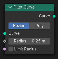
- fillet_bezier(radius=0.25, count=1, limit_radius=False)#
The Fillet Curve rounds corners on curve control points, similar to the effect of the Bevel Modifier on a 2D mesh. However, a key difference is that the rounded portions created by the Fillet Curve node are always portions of a circle.
Path#
Curve > Operations > Fillet Curve Node
Outputs:#
#0 curve: Geometry = None
- fillet_poly(radius=0.25, count=1, limit_radius=False)#
The Fillet Curve rounds corners on curve control points, similar to the effect of the Bevel Modifier on a 2D mesh. However, a key difference is that the rounded portions created by the Fillet Curve node are always portions of a circle.
Path#
Curve > Operations > Fillet Curve Node
Outputs:#
#0 curve: Geometry = None
- interpolate_curves(guide_up=(0.0, 0.0, 0.0), guide_group_id=0, points=None, point_up=(0.0, 0.0, 0.0), point_group_id=0, max_neighbors=4)#
Generate new curves on points by interpolating between existing curves. This is useful to have a smaller set of original curves to make editing easier and faster while still generating high-density curves for the viewport or a final render.
Path#
Curve > Operations > Interpolate Curves Node
Outputs:#
#0 curves: Geometry = None#1 closest_index: Integer = 0#2 closest_weight: Float = 0.0
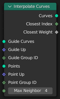
- resample(count=10, length=0.1, mode='COUNT', selection=True)#
The Resample Curve node creates a poly spline for each input spline. In the Count and Length modes, the control points of the new poly splines will have uniform spacing.
Path#
Curve > Operations > Resample Curve Node
Properties#
mode:COUNT,EVALUATED,LENGTH
Outputs:#
#0 curve: Geometry = None
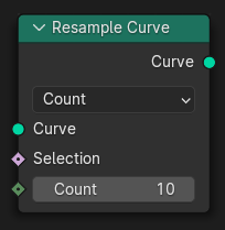
- resample_length(length=0.1, selection=True)#
The Resample Curve node creates a poly spline for each input spline. In the Count and Length modes, the control points of the new poly splines will have uniform spacing.
Path#
Curve > Operations > Resample Curve Node
Outputs:#
#0 curve: Geometry = None
- resample_evaluated(selection=True)#
The Resample Curve node creates a poly spline for each input spline. In the Count and Length modes, the control points of the new poly splines will have uniform spacing.
Path#
Curve > Operations > Resample Curve Node
Outputs:#
#0 curve: Geometry = None
- reverse(selection=True)#
The Reverse Curve node swaps the start and end of splines. The shape of the splines is not changed.
Path#
Curve > Operations > Reverse Curve Node
Outputs:#
#0 curve: Geometry = None
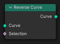
- subdivide(cuts=1)#
The Subdivide Curve node adds more control points in between existing control points on the curve input. For Bézier and poly splines, the shape of the spline will not be changed at all.
Path#
Curve > Operations > Subdivide Curve Node
Outputs:#
#0 curve: Geometry = None
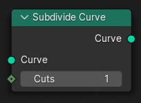
- trim_factor(start=0.0, end=1.0, selection=True)#
The Trim Curve node shortens each spline in the curve by removing sections at the start and end of each spline.
Path#
Curve > Operations > Trim Curve Node
Outputs:#
#0 curve: Geometry = None
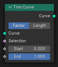
- trim_length(start=0.0, end=1.0, selection=True)#
The Trim Curve node shortens each spline in the curve by removing sections at the start and end of each spline.
Path#
Curve > Operations > Trim Curve Node
Outputs:#
#0 curve: Geometry = None
- static curve_of_point(point_index: pynodes.datasocks.Integer = None)#
The Curve of Point node retrieves the index of the curve a control point is part of. This node is conceptually similar to the Face of Corner Node.
Path#
Curve > Topology > Curve of Point Node
Outputs:#
#0 curve_index: Integer = 0#1 index_in_curve: Integer = 0
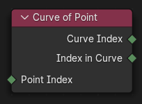
- static offset_point_in_curve(point_index: pynodes.datasocks.Integer = None, offset=0)#
The Offset Point in Curve node retrieves other points in the same curve as the input control point. This is like starting at a specific control point and walking along neighboring points toward the start or end of the curve.
Path#
Curve > Topology > Offset Point in Curve Node
Outputs:#
#0 is_valid_offset: Boolean = False#1 point_index: Integer = 0
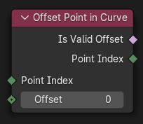
- static points_of_curve(curve_index: pynodes.datasocks.Integer = None, weights=0.0, sort_index=0)#
The Points of Curve node retrieves indices of specific control points in a curve.
Path#
Curve > Topology > Points of Curve Node
Outputs:#
#0 point_index: Integer = 0#1 total: Integer = 0
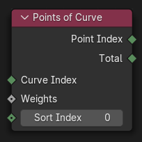
- class pynodes.geosocks.Mesh(bsocket: bpy.types.NodeSocket)#
Bases:
pynodes.geosocks.GeometryA mesh data socket
Initialization
- property domain_size#
The Domain Size outputs the size of an attribute domain on the selected geometry type, for example, the number of edges in a mesh, or the number of points in a point cloud.
Path#
Attribute > Domain Size Node
Outputs:#
#0 point_count: Integer = 0#1 edge_count: Integer = 0#2 face_count: Integer = 0#3 face_corner_count: Integer = 0
- raycast(mapping='INTERPOLATED', attribute=0.0, source_position: pynodes.datasocks.Vector = None, ray_direction=(0.0, 0.0, -1.0), ray_length=100.0)#
The Raycast node intersects rays from one geometry onto another. The source geometry is defined by the context of the node that the Raycast node is connected to. Each ray computes hit points on the target mesh and outputs normals, distances and any surface attribute specified.
Path#
Geometry > Sample > Raycast Node
Properties#
mapping:INTERPOLATED,NEAREST
Outputs:#
#0 is_hit: Boolean = False#1 hit_position: Vector = (0.0, 0.0, 0.0)#2 hit_normal: Vector = (0.0, 0.0, 0.0)#3 hit_distance: Float = 0.0#5 attribute_001: Float = 0.0
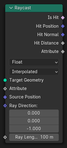
- raycast_vector(mapping='INTERPOLATED', attribute=(0.0, 0.0, 0.0), source_position: pynodes.datasocks.Vector = None, ray_direction=(0.0, 0.0, -1.0), ray_length=100.0)#
The Raycast node intersects rays from one geometry onto another. The source geometry is defined by the context of the node that the Raycast node is connected to. Each ray computes hit points on the target mesh and outputs normals, distances and any surface attribute specified.
Path#
Geometry > Sample > Raycast Node
Properties#
mapping:INTERPOLATED,NEAREST
Outputs:#
#0 is_hit: Boolean = False#1 hit_position: Vector = (0.0, 0.0, 0.0)#2 hit_normal: Vector = (0.0, 0.0, 0.0)#3 hit_distance: Float = 0.0#4 attribute: Vector = (0.0, 0.0, 0.0)
- raycast_float(mapping='INTERPOLATED', attribute=0.0, source_position: pynodes.datasocks.Vector = None, ray_direction=(0.0, 0.0, -1.0), ray_length=100.0)#
The Raycast node intersects rays from one geometry onto another. The source geometry is defined by the context of the node that the Raycast node is connected to. Each ray computes hit points on the target mesh and outputs normals, distances and any surface attribute specified.
Path#
Geometry > Sample > Raycast Node
Properties#
mapping:INTERPOLATED,NEAREST
Outputs:#
#0 is_hit: Boolean = False#1 hit_position: Vector = (0.0, 0.0, 0.0)#2 hit_normal: Vector = (0.0, 0.0, 0.0)#3 hit_distance: Float = 0.0#5 attribute_001: Float = 0.0
- raycast_color(mapping='INTERPOLATED', attribute=(0.0, 0.0, 0.0, 0.0), source_position: pynodes.datasocks.Vector = None, ray_direction=(0.0, 0.0, -1.0), ray_length=100.0)#
The Raycast node intersects rays from one geometry onto another. The source geometry is defined by the context of the node that the Raycast node is connected to. Each ray computes hit points on the target mesh and outputs normals, distances and any surface attribute specified.
Path#
Geometry > Sample > Raycast Node
Properties#
mapping:INTERPOLATED,NEAREST
Outputs:#
#0 is_hit: Boolean = False#1 hit_position: Vector = (0.0, 0.0, 0.0)#2 hit_normal: Vector = (0.0, 0.0, 0.0)#3 hit_distance: Float = 0.0#6 attribute_002: Color = (0.0, 0.0, 0.0, 0.0)
- raycast_boolean(mapping='INTERPOLATED', attribute=False, source_position: pynodes.datasocks.Vector = None, ray_direction=(0.0, 0.0, -1.0), ray_length=100.0)#
The Raycast node intersects rays from one geometry onto another. The source geometry is defined by the context of the node that the Raycast node is connected to. Each ray computes hit points on the target mesh and outputs normals, distances and any surface attribute specified.
Path#
Geometry > Sample > Raycast Node
Properties#
mapping:INTERPOLATED,NEAREST
Outputs:#
#0 is_hit: Boolean = False#1 hit_position: Vector = (0.0, 0.0, 0.0)#2 hit_normal: Vector = (0.0, 0.0, 0.0)#3 hit_distance: Float = 0.0#7 attribute_003: Boolean = False
- raycast_integer(mapping='INTERPOLATED', attribute=0, source_position: pynodes.datasocks.Vector = None, ray_direction=(0.0, 0.0, -1.0), ray_length=100.0)#
The Raycast node intersects rays from one geometry onto another. The source geometry is defined by the context of the node that the Raycast node is connected to. Each ray computes hit points on the target mesh and outputs normals, distances and any surface attribute specified.
Path#
Geometry > Sample > Raycast Node
Properties#
mapping:INTERPOLATED,NEAREST
Outputs:#
#0 is_hit: Boolean = False#1 hit_position: Vector = (0.0, 0.0, 0.0)#2 hit_normal: Vector = (0.0, 0.0, 0.0)#3 hit_distance: Float = 0.0#8 attribute_004: Integer = 0
- merge_by_distance(distance=0.001, mode='ALL', selection=True)#
The Merge by Distance node merges selected mesh vertices or point cloud points within a given distance, merging surrounding geometry where necessary. This operation is similar to the Merge by Distance operator or the Weld Modifier.
Path#
Geometry > Operations > Merge by Distance Node
Properties#
mode:ALL,CONNECTED
Outputs:#
#0 geometry: Geometry = None
- merge_connected(distance=0.001, selection=True)#
The Merge by Distance node merges selected mesh vertices or point cloud points within a given distance, merging surrounding geometry where necessary. This operation is similar to the Merge by Distance operator or the Weld Modifier.
Path#
Geometry > Operations > Merge by Distance Node
Properties#
mode:ALL,CONNECTED
Outputs:#
#0 geometry: Geometry = None
- property edge_angle#
The Edge Angle node calculates the angle in radians between two faces that meet at an edge. For the Face, Face Corner, and Point domains, the node uses simple domain interpolation to move values from the mesh’s edges.
Path#
Mesh > Read > Edge Angle Node
Outputs:#
#0 unsigned_angle: Float = 0.0#1 signed_angle: Float = 0.0
- property edge_neighbors#
The Edge Neighbors node outputs topology information relating to each edge of a mesh.
Path#
Mesh > Read > Edge Neighbors Node
Outputs:#
#0 face_count: Integer = 0
- property edge_vertices#
The Edge Vertices node outputs the position and index of the two vertices of each of a mesh’s edges.
Path#
Mesh > Read > Edge Vertices Node
Outputs:#
#0 vertex_index_1: Integer = 0#1 vertex_index_2: Integer = 0#2 position_1: Vector = (0.0, 0.0, 0.0)#3 position_2: Vector = (0.0, 0.0, 0.0)
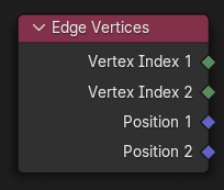
- static edges_to_face_groups(boundary_edges=True)#
The Edges to Face Groups node group faces into regions surrounded by the selected boundary edges.
Path#
Mesh > Read > Edges to Face Groups Node
Outputs:#
#0 face_group_id: Integer = 0
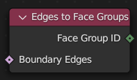
- property face_area#
The Face Area node outputs the surface area of a mesh’s faces. The units are in Blender units no matter the unit system, equivalent to meters-squared at the default unit scale.
Path#
Mesh > Read > Face Area Node
Outputs:#
#0 area: Float = 0.0
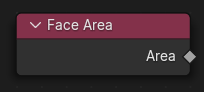
- property face_neighbors#
The Face Neighbors node outputs topology information relating to each face of a mesh.
Path#
Mesh > Read > Face Neighbors Node
Outputs:#
#0 vertex_count: Integer = 0#1 face_count: Integer = 0
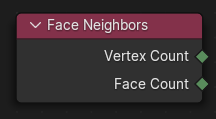
- static faceset_boundaries(face_set=0)#
The Face Group Boundaries Node finds the edges which lie on the boundaries of specified regions. These edges could be used to mark seams for UV unwrapping, for example.
Path#
Mesh > Read > Face Group Boundaries Node
Outputs:#
#0 boundary_edges: Boolean = False
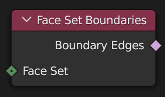
- static face_is_planar(threshold=0.01)#
The Is Face Planar node outputs whether every triangle of a quads or N-gons is on the same plane as all of the others, in other words, if they have the same normal.
Path#
Mesh > Read > Is Face Planar Node
Outputs:#
#0 planar: Boolean = False
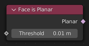
- property is_shade_smooth#
The Is Shade Smooth node outputs true for each face of the mesh if that face is marked to render smooth shaded. Otherwise, if the face is marked to render as flat shaded, so the node outputs false.
Path#
Mesh > Read > Is Shade Smooth Node
Outputs:#
#0 smooth: Boolean = False
- property mesh_island#
The Mesh Island node outputs information about separate connected regions, or “islands” of a mesh. Whenever two vertices are connected together by an edge, they are considered as part of the same island, and will have the same Island Index output.
Path#
Mesh > Read > Mesh Island Node
Outputs:#
#0 island_index: Integer = 0#1 island_count: Integer = 0
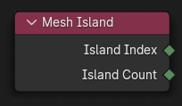
- static shortest_edge_paths(end_vertex=False, edge_cost=1.0)#
The Shortest Edge Paths node finds paths along mesh edges to a selection of end vertices. The cost used to define “shortest” can be set to anything. By default there is a constant cost for every edge, but a typical input would be the length of each edge.
Path#
Mesh > Read > Shortest Edge Paths Node
Outputs:#
#0 next_vertex_index: Integer = 0#1 total_cost: Float = 0.0
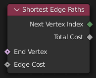
- property vertex_neighbors#
The Vertex Neighbors node outputs topology information relating to each vertex of a mesh.
Path#
Mesh > Read > Vertex Neighbors Node
Outputs:#
#0 vertex_count: Integer = 0#1 face_count: Integer = 0
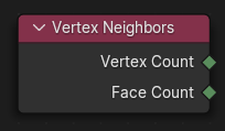
- nearest_surface(data_type='FLOAT', value_float=0.0, value_int=0, value_vector=(0.0, 0.0, 0.0), value_color=(0.0, 0.0, 0.0, 0.0), value_bool=False, sample_position: pynodes.datasocks.Vector = None)#
The Sample Nearest Surface node finds values at the closest points on the surface of a source mesh geometry. Non-face attributes are interpolated across the surface.
Path#
Mesh > Sample > Sample Nearest Surface Node
Properties#
data_type:FLOAT,INT,FLOAT_VECTOR,FLOAT_COLOR,BOOLEAN
Outputs:#
#0 value_float: Float = 0.0#1 value_int: Integer = 0#2 value_vector: Vector = (0.0, 0.0, 0.0)#3 value_color: Color = (0.0, 0.0, 0.0, 0.0)#4 value_bool: Boolean = False
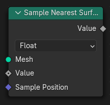
- nearest_surface_float(value_float=0.0, sample_position: pynodes.datasocks.Vector = None)#
The Sample Nearest Surface node finds values at the closest points on the surface of a source mesh geometry. Non-face attributes are interpolated across the surface.
Path#
Mesh > Sample > Sample Nearest Surface Node
Outputs:#
#0 value_float: Float = 0.0
- nearest_surface_integer(value_int=0, sample_position: pynodes.datasocks.Vector = None)#
The Sample Nearest Surface node finds values at the closest points on the surface of a source mesh geometry. Non-face attributes are interpolated across the surface.
Path#
Mesh > Sample > Sample Nearest Surface Node
Outputs:#
#1 value_int: Integer = 0
- nearest_surface_vector(value_vector=(0.0, 0.0, 0.0), sample_position: pynodes.datasocks.Vector = None)#
The Sample Nearest Surface node finds values at the closest points on the surface of a source mesh geometry. Non-face attributes are interpolated across the surface.
Path#
Mesh > Sample > Sample Nearest Surface Node
Outputs:#
#2 value_vector: Vector = (0.0, 0.0, 0.0)
- nearest_surface_color(value_color=(0.0, 0.0, 0.0, 0.0), sample_position: pynodes.datasocks.Vector = None)#
The Sample Nearest Surface node finds values at the closest points on the surface of a source mesh geometry. Non-face attributes are interpolated across the surface.
Path#
Mesh > Sample > Sample Nearest Surface Node
Outputs:#
#3 value_color: Color = (0.0, 0.0, 0.0, 0.0)
- nearest_surface_boolean(value_bool=False, sample_position: pynodes.datasocks.Vector = None)#
The Sample Nearest Surface node finds values at the closest points on the surface of a source mesh geometry. Non-face attributes are interpolated across the surface.
Path#
Mesh > Sample > Sample Nearest Surface Node
Outputs:#
#4 value_bool: Boolean = False
- sample_uv_surface_float(value_float=0.0, source_uv_map=(0.0, 0.0, 0.0), sample_uv=(0.0, 0.0, 0.0))#
The Sample UV Surface node finds values on a mesh’s surface at specific UV locations. Internally the process is a “reverse UV lookup” from a location in 2D space. The node then finds the face that corresponds to each UV coordinate, and the location within that face.
Path#
Mesh > Sample > Sample UV Surface Node
Outputs:#
#0 value_float: Float = 0.0#5 is_valid: Boolean = False
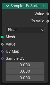
- sample_uv_surface_integer(value_int=0.0, source_uv_map=(0.0, 0.0, 0.0), sample_uv=(0.0, 0.0, 0.0))#
The Sample UV Surface node finds values on a mesh’s surface at specific UV locations. Internally the process is a “reverse UV lookup” from a location in 2D space. The node then finds the face that corresponds to each UV coordinate, and the location within that face.
Path#
Mesh > Sample > Sample UV Surface Node
Outputs:#
#1 value_int: Integer = 0#5 is_valid: Boolean = False
- sample_uv_surface_vector(value_vector=(0.0, 0.0, 0.0), source_uv_map=(0.0, 0.0, 0.0), sample_uv=(0.0, 0.0, 0.0))#
The Sample UV Surface node finds values on a mesh’s surface at specific UV locations. Internally the process is a “reverse UV lookup” from a location in 2D space. The node then finds the face that corresponds to each UV coordinate, and the location within that face.
Path#
Mesh > Sample > Sample UV Surface Node
Outputs:#
#2 value_vector: Vector = (0.0, 0.0, 0.0)#5 is_valid: Boolean = False
- sample_uv_surface_color(value_color=(0.0, 0.0, 0.0, 0.0), source_uv_map=(0.0, 0.0, 0.0), sample_uv=(0.0, 0.0, 0.0))#
The Sample UV Surface node finds values on a mesh’s surface at specific UV locations. Internally the process is a “reverse UV lookup” from a location in 2D space. The node then finds the face that corresponds to each UV coordinate, and the location within that face.
Path#
Mesh > Sample > Sample UV Surface Node
Outputs:#
#3 value_color: Color = (0.0, 0.0, 0.0, 0.0)#5 is_valid: Boolean = False
- sample_uv_surface_boolean(value_bool=False, source_uv_map=(0.0, 0.0, 0.0), sample_uv=(0.0, 0.0, 0.0))#
The Sample UV Surface node finds values on a mesh’s surface at specific UV locations. Internally the process is a “reverse UV lookup” from a location in 2D space. The node then finds the face that corresponds to each UV coordinate, and the location within that face.
Path#
Mesh > Sample > Sample UV Surface Node
Outputs:#
#4 value_bool: Boolean = False#5 is_valid: Boolean = False
- set_shade_smooth(shade_smooth=True, domain='FACE', selection=True)#
The Set Shade Smooth node controls whether the mesh’s faces look smooth in the viewport and renders. The input node for this data is the Is Shade Smooth node.
In-Place Operation
Path#
Mesh > Write > Set Shade Smooth Node
Properties#
domain(New in Blender 4.0):FACE,EDGE
Outputs:#
#0 geometry: Geometry = None
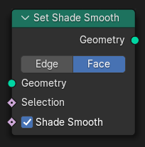
- dual_mesh(keep_boundaries=False)#
The Dual Mesh Node converts a mesh into it’s dual, i.e. faces are turned into vertices and vertices are turned into faces. This also means that attributes which were on the face domain are transferred to the point domain in the dual mesh.
Path#
Mesh > Operations > Dual Mesh Node
Outputs:#
#0 dual_mesh: Geometry = None
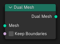
- edge_paths_to_curves(start_vertices=True, next_vertex_index=-1)#
The Edge Paths to Curves node output curves that follow paths across mesh edges.
Path#
Mesh > Operations > Edge Paths to Curves Node
Outputs:#
#0 curves: Geometry = None
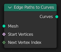
- static edge_paths_to_selection(start_vertices=True, next_vertex_index=-1)#
The Edge Paths to Selection node follows paths across mesh edges and outputs a selection of every visited edge.
Path#
Mesh > Operations > Edge Paths to Selection Node
Outputs:#
#0 selection: Boolean = False
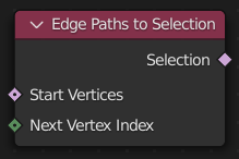
- extrude(offset_scale=1.0, offset: pynodes.datasocks.Vector = None, individual=True, mode='FACES', selection=True)#
The Extrude Mesh Node generates new vertices, edges, or faces, on selected geometry and transforms them based on an offset.
Path#
Mesh > Operations > Extrude Mesh Node
Properties#
mode:FACES,VERTICES,EDGES
Outputs:#
#0 mesh: Geometry = None#1 top: Boolean = False#2 side: Boolean = False
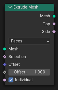
- extrude_faces(offset_scale=1.0, offset: pynodes.datasocks.Vector = None, individual=True, selection=True)#
The Extrude Mesh Node generates new vertices, edges, or faces, on selected geometry and transforms them based on an offset.
Path#
Mesh > Operations > Extrude Mesh Node
Outputs:#
#0 mesh: Geometry = None#1 top: Boolean = False#2 side: Boolean = False
- extrude_vertices(offset_scale=1.0, offset: pynodes.datasocks.Vector = None, individual=True, selection=True)#
The Extrude Mesh Node generates new vertices, edges, or faces, on selected geometry and transforms them based on an offset.
Path#
Mesh > Operations > Extrude Mesh Node
Outputs:#
#0 mesh: Geometry = None#1 top: Boolean = False#2 side: Boolean = False
- extrude_edges(offset_scale=1.0, offset: pynodes.datasocks.Vector = None, individual=True, selection=True)#
The Extrude Mesh Node generates new vertices, edges, or faces, on selected geometry and transforms them based on an offset.
Path#
Mesh > Operations > Extrude Mesh Node
Outputs:#
#0 mesh: Geometry = None#1 top: Boolean = False#2 side: Boolean = False
- flip_faces(selection=True)#
The Flip Faces Node reverses the order of the vertices and edges of each selected face. The most common use of this node is to flip the normals of a face. Any face corner domain attributes of selected faces are also reversed.
Path#
Mesh > Operations > Flip Faces Node
Outputs:#
#0 mesh: Geometry = None
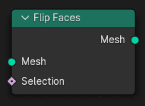
- mesh_union(*others: pynodes.geosocks.Mesh, self_intersection=False, hole_tolerant=False)#
The Mesh Boolean Node allows you to cut, subtract, and join the geometry of two inputs. This node offers the same operations as the Boolean modifier.
Path#
Mesh > Operations > Mesh Boolean Node
Outputs:#
#0 mesh: Geometry = None#1 intersecting_edges: Boolean = False
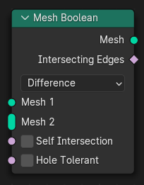
- mesh_intersect(*others: pynodes.geosocks.Mesh, self_intersection=False, hole_tolerant=False)#
The Mesh Boolean Node allows you to cut, subtract, and join the geometry of two inputs. This node offers the same operations as the Boolean modifier.
Path#
Mesh > Operations > Mesh Boolean Node
Outputs:#
#0 mesh: Geometry = None#1 intersecting_edges: Boolean = False
- mesh_difference(*others: pynodes.geosocks.Mesh, self_intersection=False, hole_tolerant=False)#
The Mesh Boolean Node allows you to cut, subtract, and join the geometry of two inputs. This node offers the same operations as the Boolean modifier.
Path#
Mesh > Operations > Mesh Boolean Node
Outputs:#
#0 mesh: Geometry = None#1 intersecting_edges: Boolean = False
- to_curve(selection=True)#
The Mesh to Curve node generates a curve from a mesh. The result is a poly spline, with a point for every selected vertex on the mesh. Any intersection of more than two selected edges will cause a break in the spline. Meaning that if a the mesh has grid-like topology and a continuous spline is desired, the Selection input is very important.
Path#
Mesh > Operations > Mesh to Curve Node
Outputs:#
#0 curve: Geometry = None
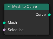
- to_points(mode='VERTICES', position: pynodes.datasocks.Vector = None, radius=0.05, selection=True)#
The Mesh to Points node generates a point cloud from a mesh.
Path#
Mesh > Operations > Mesh to Points Node
Properties#
mode:VERTICES,EDGES,FACES,CORNERS
Outputs:#
#0 points: Geometry = None
- to_volume(resolution_mode='VOXEL_AMOUNT', density=1.0, voxel_size=0.3, voxel_amount=64.0, exterior_band_width=0.1, interior_band_width=0.0, fill_volume=True)#
The Mesh to Volume node creates a fog volumes based on the shape of a mesh. The volume is created with a grid of the name “density”.
Path#
Mesh > Operations > Mesh to Volume Node
Properties#
resolution_mode:VOXEL_AMOUNT,VOXEL_SIZE
Outputs:#
#0 volume: Geometry = None
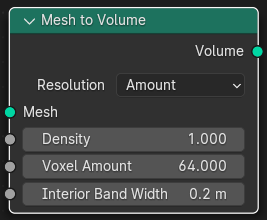
- to_sdf_volume(resolution_mode='VOXEL_AMOUNT', voxel_size=0.3, voxel_amount=64.0, half_band_width=3.0)#
The Mesh to Volume node creates a fog volumes based on the shape of a mesh. The volume is created with a grid of the name “density”.
Experimental node
Path#
Mesh > Operations > Mesh to SDF Volume Node
Properties#
resolution_mode:VOXEL_AMOUNT,VOXEL_SIZE
Outputs:#
#0 volume: Volume = None
- scale_elements(scale=1.0, center: pynodes.datasocks.Vector = None, axis=(1.0, 0.0, 0.0), domain='FACE', scale_mode='UNIFORM', selection=True)#
The Scale Elements Node scales groups of connected edges and faces. When multiple selected faces/edges share the same vertices, they are scaled together. The center and scaling factor is averaged in this case.
Path#
Mesh > Operations > Scale Elements Node
Properties#
domain:FACE,EDGEscale_mode:UNIFORM,SINGLE_AXIS
Outputs:#
#0 geometry: Geometry = None
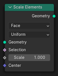
- split_edges(selection=True)#
Like the Edge Split Modifier, the Split Edges node splits and duplicates edges within a mesh, breaking ‘links’ between faces around those split edges.
Path#
Mesh > Operations > Split Edges Node
Outputs:#
#0 mesh: Geometry = None
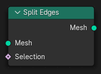
- subdivide_mesh(level=1)#
The Subdivide Mesh node adds new faces to mesh geometry using a simple interpolation for deformation.
Path#
Mesh > Operations > Subdivide Mesh Node
Outputs:#
#0 mesh: Geometry = None
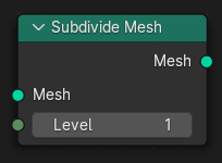
- subdivision_surface(uv_smooth='PRESERVE_BOUNDARIES', boundary_smooth='ALL', level=1, edge_crease=0.0, vertex_crease=0.0)#
The Subdivision Surface node adds new faces to mesh geometry using a Catmull-Clark subdivision method.
Path#
Mesh > Operations > Subdivision Surface Node
Properties#
boundary_smooth:ALL,PRESERVE_CORNERSuv_smooth:PRESERVE_BOUNDARIES,NONE,PRESERVE_CORNERS,PRESERVE_CORNERS_AND_JUNCTIONS,PRESERVE_CORNERS_JUNCTIONS_AND_CONCAVE,SMOOTH_ALL
Outputs:#
#0 mesh: Geometry = None
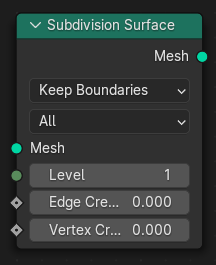
- triangulate(quad_method='SHORTEST_DIAGONAL', ngon_method='BEAUTY', minimum_vertices=4, selection=True)#
The Triangulate node converts all faces in a mesh (quads and n-gons) to triangular faces. It functions the same as the Triangulate tool in Edit Mode.
Path#
Mesh > Operations > Triangulate Node
Properties#
quad_method:SHORTEST_DIAGONAL,BEAUTY,FIXED,FIXED_ALTERNATE,LONGEST_DIAGONALngon_method:BEAUTY,CLIP
Outputs:#
#0 mesh: Geometry = None
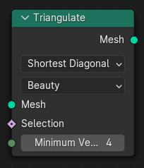
- static corners_of_face(face_index: pynodes.datasocks.Integer = None, weights=0.0, sort_index=0)#
The Corners of Face node gives access to specific corners of input faces.
Path#
Mesh > Topology > Corners of Face Node
Outputs:#
#0 corner_index: Integer = 0#1 total: Integer = 0
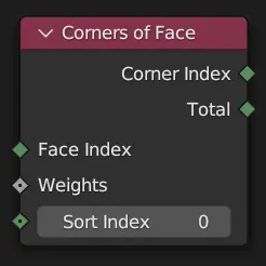
- static corners_of_vertex(vertex_index: pynodes.datasocks.Integer = None, weights=0.0, sort_index=0)#
The Corners of Vertex node retrieves face corners attached to each vertex. The node first gathers a list of the corners of all faces connected to the vertex. That list is then sorted based on the values of the Sort Weight input. The Total output is the number of connected faces/corners, and the Corner Index output is one of those corners, chosen with the Sort Index input.
Path#
Mesh > Topology > Corners of Vertex Node
Outputs:#
#0 corner_index: Integer = 0#1 total: Integer = 0
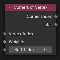
- static edges_of_corner(corner_index: pynodes.datasocks.Integer = None)#
The Edges of Corner node retrieves the edges on both sides of a face corner.
Path#
Mesh > Topology > Edges of Corner Node
Outputs:#
#0 next_edge_index: Integer = 0#1 previous_edge_index: Integer = 0
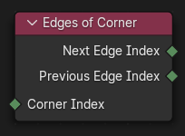
- static edges_of_vertex(vertex_index: pynodes.datasocks.Integer = None, weights=0.0, sort_index=0)#
The Edges of Vertex node retrieves the edges connected to each vertex. Each vertex is connected to several edges. The node first collects a list of those edges, then sorts them based on the Sort Weight input. The Total output is the number of edges in that list, and the Edge Index output is one of those edges chosen with the Sort Index input.
Path#
Mesh > Topology > Edges of Vertex Node
Outputs:#
#0 edge_index: Integer = 0#1 total: Integer = 0
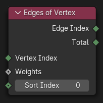
- static face_of_corner(corner_index: pynodes.datasocks.Integer = None)#
The Face of Corner node retrieves the face a face corner is part of.
Path#
Mesh > Topology > Face of Corner Node
Outputs:#
#0 face_index: Integer = 0#1 index_in_face: Integer = 0
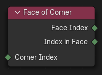
- static offset_corner_in_face(corner_index: pynodes.datasocks.Integer = None, offset=0)#
The Offset Corner in Face node retrieves other corners in the same face as the input face corner. This is like “rotating” the input corner around in its face.
Path#
Mesh > Topology > Offset Corner in Face Node
Outputs:#
#0 corner_index: Integer = 0
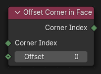
- static vertex_of_corner(corner_index: pynodes.datasocks.Integer = None)#
The Vertex of Corner node outputs the index of the vertex that a face corner is attached to.
Path#
Mesh > Topology > Vertex of Corner Node
Outputs:#
#0 vertex_index: Integer = 0
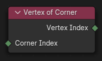
- pack_uv_islands(uv=(0.0, 0.0, 0.0), margin=0.001, rotate=True, selection=True)#
The Pack UV Islands Node scales islands of a UV map and moves them so they fill the UV space as much as possible.
Path#
Mesh > UV > Pack UV Islands Node
Outputs:#
#0 uv: Vector = (0.0, 0.0, 0.0)
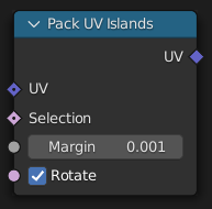
- uv_unwrap(method='ANGLE_BASED', seam=False, margin=0.001, fill_holes=True, selection=True)#
The UV Unwrap Node generates a UV map islands based on a selection of seam edges. The node implicitly performs a Pack Islands operation upon completion, because the results may not be generally useful otherwise.
Path#
Mesh > UV > UV Unwrap Node
Properties#
method:ANGLE_BASED,CONFORMAL
Outputs:#
#0 uv: Vector = (0.0, 0.0, 0.0)
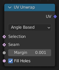
- distribute_points_on_faces(distribute_method='RANDOM', use_legacy_normal=False, distance_min=0.0, density_max=10.0, density=10.0, density_factor=1.0, seed=0, selection=True)#
The Distribute Points on Faces node places points on the surface of the input geometry object. Point, corner, and polygon attributes of the input geometry are transferred to the generated points. That includes vertex weights and UV maps. Additionally, the node has Normal and Rotation outputs.
Path#
Point > Distribute Points on Faces
Properties#
distribute_method:RANDOM,POISSON
Outputs:#
#0 points: Geometry = None#1 normal: Vector = (0.0, 0.0, 0.0)#2 rotation: Vector = (0.0, 0.0, 0.0)
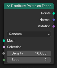
- class pynodes.geosocks.Points(bsocket: bpy.types.NodeSocket)#
Bases:
pynodes.geosocks.GeometryA points cloud data socket
Initialization
- capture_vector(value=(0.0, 0.0, 0.0))#
The Capture Attribute node stores the result of a field on a geometry, and outputs the data as a node socket so it can be used by other nodes.
In-Place Operation
Path#
Attribute > Capture Attribute Node
Outputs:#
#0 geometry: Geometry = None#1 attribute: Vector = (0.0, 0.0, 0.0)
- to_curves(curve_group_id=0, weight=0.0)#
The Points to Curves node generates a Curves geometry by taking all points and inserting them to new curves. All Attributes from points are propagated to Curve Points. Built-in curves attributes stored in points will be ignored.
New in Blender 4.0.0
Path#
Point > Points to Curves Node
Outputs:#
#0 curves: Curve = None
- property domain_size#
The Domain Size outputs the size of an attribute domain on the selected geometry type, for example, the number of edges in a mesh, or the number of points in a point cloud.
Path#
Attribute > Domain Size Node
Outputs:#
#0 point_count: Integer = 0
- property point_count#
The Domain Size outputs the size of an attribute domain on the selected geometry type, for example, the number of edges in a mesh, or the number of points in a point cloud.
Path#
Attribute > Domain Size Node
Outputs:#
#0 point_count: Integer = 0
- merge_by_distance(distance=0.001, mode='ALL', selection=True)#
The Merge by Distance node merges selected mesh vertices or point cloud points within a given distance, merging surrounding geometry where necessary. This operation is similar to the Merge by Distance operator or the Weld Modifier.
Path#
Geometry > Operations > Merge by Distance Node
Properties#
mode:ALL,CONNECTED
Outputs:#
#0 geometry: Geometry = None
- to_vertices(selection=True)#
The Points to Vertices node generate a mesh vertex in the output geometry for each point cloud point in the input geometry.
Path#
Point > Points to Vertices Node
Outputs:#
#0 mesh: Geometry = None
- to_volume(resolution_mode='VOXEL_AMOUNT', density=1.0, voxel_size=0.3, voxel_amount=64.0, radius=0.5)#
The Points to Volume node generates a fog volume sphere around every point in the input geometry. The new volume grid is named “density”.
Path#
Point > Points to Volume Node
Properties:#
resolution_mode:VOXEL_AMOUNT,VOXEL_SIZE
Outputs:#
#0 volume: Geometry = None
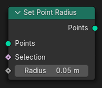
- class pynodes.geosocks.Instances(bsocket: bpy.types.NodeSocket)#
Bases:
pynodes.geosocks.GeometryA instances data socket
Initialization
- property domain_size#
The Domain Size outputs the size of an attribute domain on the selected geometry type, for example, the number of edges in a mesh, or the number of points in a point cloud.
Path#
Attribute > Domain Size Node
Outputs:#
#5 instance_count: Integer = 0
- capture_integer(value_int=0)#
The Capture Attribute node stores the result of a field on a geometry, and outputs the data as a node socket so it can be used by other nodes.
In-Place Operation
Path#
Attribute > Capture Attribute Node
Outputs:#
#0 geometry: Geometry = None#5 attribute: Integer = 0
- store_named_attribute(name: str, value, domain='INSTANCE', selection=True)#
- sample_float_at_index(value_float=0.0, index=0, clamp=False)#
The Sample Index node retrieves values from a source geometry at a specific index.
Path#
Geometry > Sample > Sample Index Node
Outputs:#
#0 value_float: Float = 0.0
- sample_integer_at_index(value_int=0, index=0, clamp=False)#
The Sample Index node retrieves values from a source geometry at a specific index.
Path#
Geometry > Sample > Sample Index Node
Outputs:#
#1 value_int: Integer = 0
- sample_vector_at_index(value_vector=(0.0, 0.0, 0.0), index=0, clamp=False)#
The Sample Index node retrieves values from a source geometry at a specific index.
Path#
Geometry > Sample > Sample Index Node
Outputs:#
#2 value_vector: Vector = (0.0, 0.0, 0.0)
- sample_color_at_index(value_color=(0.0, 0.0, 0.0, 0.0), index=0, clamp=False)#
The Sample Index node retrieves values from a source geometry at a specific index.
Path#
Geometry > Sample > Sample Index Node
Outputs:#
#3 value_color: Color = (0.0, 0.0, 0.0, 0.0)
- sample_boolean_at_index(value_bool=False, index=0, clamp=False)#
The Sample Index node retrieves values from a source geometry at a specific index.
Path#
Geometry > Sample > Sample Index Node
Outputs:#
#4 value_bool: Boolean = False
- separate(selection=True)#
The Separate Geometry node produces two geometry outputs. Based on the Selection input, the input geometry is split between the two outputs.
Path#
Geometry > Operations > Separate Geometry Node
Outputs:#
#0 selection: Geometry = None#1 inverted: Geometry = None
- scale_elements(domain='FACE', scale_mode='UNIFORM', scale=1.0, center: pynodes.datasocks.Vector = None, axis=(1.0, 0.0, 0.0), selection=True)#
The Scale Elements Node scales groups of connected edges and faces. When multiple selected faces/edges share the same vertices, they are scaled together. The center and scaling factor is averaged in this case.
Path#
Mesh > Operations > Scale Elements Node
Properties#
domain:FACE,EDGEscale_mode:UNIFORM,SINGLE_AXIS
Outputs:#
#0 geometry: Geometry = None
- to_points(position: pynodes.datasocks.Vector = None, radius=0.05, selection=True)#
The Instances to Points node generates points at the origins of top-level instances. Attributes on the instance domain are moved to the point cloud points.
Path#
Instances > Instances to Points Node
Outputs:#
#0 points: Geometry = None

- rotate_instances(rotation=(0.0, 0.0, 0.0), pivot_point=(0.0, 0.0, 0.0), local_space=True, selection=True)#
The Rotate Instances node rotates geometry instances in local or global space.
Path#
Instances > Rotate Instances Node
Outputs:#
#0 instances: Geometry = None
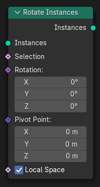
- scale_instances(scale=(1.0, 1.0, 1.0), center=(0.0, 0.0, 0.0), local_space=True, selection=True)#
The Scale Instances node scales geometry instances in local or global space.
Path#
Instances > Scale Instances Node
Outputs:#
#0 instances: Geometry = None
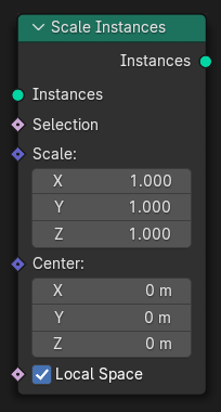
- translate_instances(translation=(0.0, 0.0, 0.0), local_space=True, selection=True)#
The Translate Instances node moves top-level geometry instances in local or global space.
Path#
Instances > Translate Instances Node
Outputs:#
#0 instances: Geometry = None
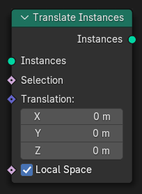
- realize_instances(legacy_behavior=False)#
The Realize Instances node makes any instances (efficient duplicates of the same geometry) into real geometry data. This makes it possible to affect each instance individually, whereas without this node, the exact same changes are applied to every instance of the same geometry. However, performance can become much worse when the input contains many instances of complex geometry, which is a fundamental limitation when procedurally processing geometry.
Path#
Instances > Realize Instances Node
Outputs:#
#0 geometry: Geometry = None
- class pynodes.geosocks.Volume(bsocket: bpy.types.NodeSocket)#
Bases:
pynodes.geosocks.GeometryA volume data socket
Initialization
- distribute_points_random(density=1.0, seed=0)#
The Distribute Points in Volume node creates points inside of volume grids. The node has two basic modes of operation: distributing points randomly, or in a regular grid. Both methods operate on all of the float grids in the volume.
Path#
Point > Distribute Points in Volume
Outputs:#
#0 points: Geometry = None
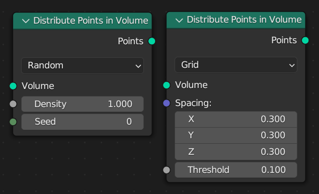
- distribute_points_grid(spacing=(0.3, 0.3, 0.3), threshold=0.1)#
The Distribute Points in Volume node creates points inside of volume grids. The node has two basic modes of operation: distributing points randomly, or in a regular grid. Both methods operate on all of the float grids in the volume.
Path#
Point > Distribute Points in Volume
Outputs:#
#0 points: Geometry = None
- to_mesh(resolution_mode='GRID', voxel_size=0.3, voxel_amount=64.0, threshold=0.1, adaptivity=0.0)#
The Volume to Mesh node generates a mesh on the “surface” of a volume. The surface is defined by a threshold value. All voxels with a larger value than the threshold are considered to be inside.
Path#
Volume > Volume to Mesh Node
Properties:#
resolution_mode:GRID,VOXEL_AMOUNT,VOXEL_SIZE
Outputs:#
#0 mesh: Geometry = None
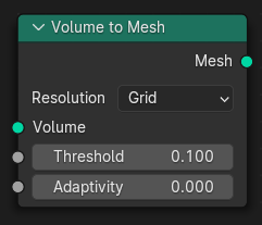
- pynodes.geosocks.CurveArc(resolution=16, radius=1.0, start_angle=math.radians(0.0), sweep_angle=math.radians(315.0), connect_center=False, invert_arc=False)#
The Arc node generates a poly spline arc. The node has two modes, Radius and Points.
Path#
Curve > Primitives > Arc Node
Outputs:#
#0 curve: Geometry = None
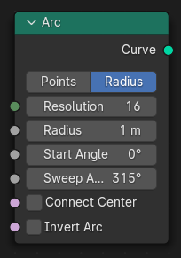
- pynodes.geosocks.CurveArcPoints(resolution=16, start=(-1.0, 0.0, 0.0), middle=(0.0, 2.0, 0.0), end=(1.0, 0.0, 0.0), offset_angle=math.radians(0.0), connect_center=False, invert_arc=False)#
The Arc node generates a poly spline arc. The node has two modes, Radius and Points.
Path#
Curve > Primitives > Arc Node
Outputs:#
#0 curve: Geometry = None#1 center: Vector = (0.0, 0.0, 0.0)#2 normal: Vector = (0.0, 0.0, 0.0)#3 radius: Float = 0.0
- pynodes.geosocks.BezierSegment(mode='POSITION', resolution=16, start=(-1.0, 0.0, 0.0), start_handle=(-0.5, 0.5, 0.0), end_handle=(0.0, 0.0, 0.0), end=(1.0, 0.0, 0.0))#
The Bézier Segment node generates a 2D Bézier spline from the given control points and handles.
Path#
Curve > Primitives > Bézier Segment Node
Properties#
mode:POSITION,OFFSET
Outputs:#
#0 curve: Geometry = None
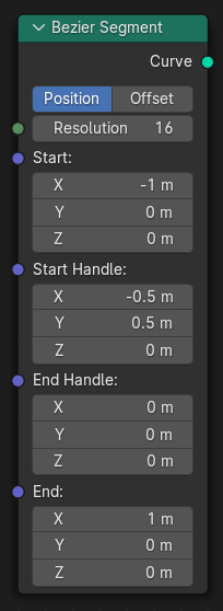
- pynodes.geosocks.CurveCircle(radius=1.0, resolution=32)#
The Curve Circle node generates a poly spline circle.
Path#
Curve > Primitives > Curve Circle Node
Outputs:#
#0 curve: Geometry = None
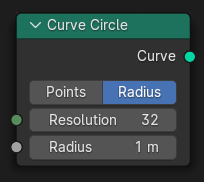
- pynodes.geosocks.CurveCirclePoints(resolution=32, point_1=(-1.0, 0.0, 0.0), point_2=(0.0, 1.0, 0.0), point_3=(1.0, 0.0, 0.0))#
The Curve Circle node generates a poly spline circle.
Path#
Curve > Primitives > Curve Circle Node
Outputs:#
#0 curve: Geometry = None#1 center: Vector = (0.0, 0.0, 0.0)
- pynodes.geosocks.CurveLine(start=(0.0, 0.0, 0.0), end=(0.0, 0.0, 1.0), direction=(0.0, 0.0, 1.0), length=1.0, mode='POINTS')#
The Curve Line node generates poly spline line.
Path#
Curve > Primitives > Curve Line Node
Properties#
mode:POINTS,DIRECTION
Outputs:#
#0 curve: Geometry = None
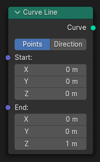
- pynodes.geosocks.CurveSpiral(resolution=32, rotations=2.0, start_radius=1.0, end_radius=2.0, height=2.0, reverse=False)#
The Curve Spiral node generates a poly spline in a spiral shape. It can be used to create springs or other similar objects. By default the spiral twists in a clockwise fashion.
Path#
Curve > Primitives > Curve Spiral Node
Outputs:#
#0 curve: Geometry = None
- pynodes.geosocks.CurveQuadraticBezier(resolution=16, start=(-1.0, 0.0, 0.0), middle=(0.0, 2.0, 0.0), end=(1.0, 0.0, 0.0))#
The Quadratic Bézier node generates a poly spline curve from the given control points. The generated shape is a parabola.
Path#
Curve > Primitives > Quadratic Bézier Node
Outputs:#
#0 curve: Geometry = None
- pynodes.geosocks.Rectangle(width=2.0, height=2.0)#
The Quadrilateral node generates a polygon with four points, with different modes.
Path#
Curve > Primitives > Quadrilateral Node
Outputs:#
#0 curve: Geometry = None
- pynodes.geosocks.Parallelogram(width=2.0, height=2.0, offset=1.0)#
The Quadrilateral node generates a polygon with four points, with different modes.
Path#
Curve > Primitives > Quadrilateral Node
Outputs:#
#0 curve: Geometry = None
- pynodes.geosocks.Trapezoid(height=2.0, bottom_width=4.0, top_width=2.0, offset=1.0)#
The Quadrilateral node generates a polygon with four points, with different modes.
Path#
Curve > Primitives > Quadrilateral Node
Outputs:#
#0 curve: Geometry = None
- pynodes.geosocks.Kite(width=2.0, bottom_height=3.0, top_height=1.0)#
The Quadrilateral node generates a polygon with four points, with different modes.
Path#
Curve > Primitives > Quadrilateral Node
Outputs:#
#0 curve: Geometry = None
- pynodes.geosocks.Quadrangle(point_1=(-1.0, -1.0, 0.0), point_2=(1.0, -1.0, 0.0), point_3=(1.0, 1.0, 0.0), point_4=(-1.0, 1.0, 0.0))#
The Quadrilateral node generates a polygon with four points, with different modes.
Path#
Curve > Primitives > Quadrilateral Node
Outputs:#
#0 curve: Geometry = None
- pynodes.geosocks.CurveStar(points=8, inner_radius=1.0, outer_radius=2.0, twist=math.radians(0.0))#
The Star node generates a poly spline in a star pattern by connecting alternating points of two circles. The points on the inner circle are offset by a rotation so that they lie in between the points on the outer circle. This offset can be changed with the twist input.
Path#
Curve > Primitives > Star Node
Outputs:#
#0 curve: Geometry = None#1 outer_points: Boolean = False
- pynodes.geosocks.MeshCone(fill_type='NGON', vertices=32, side_segments=1, fill_segments=1, radius_top=0.0, radius_bottom=1.0, depth=2.0)#
The Cone node generates a cone mesh that is optionally truncated.
Path#
Mesh > Primitives > Cone Node
Properties#
fill_type:NGON,NONE,TRIANGLE_FAN
Outputs:#
#0 mesh: Geometry = None#1 top: Boolean = False#2 bottom: Boolean = False#3 side: Boolean = False#4 uv_map: Vector = (0.0, 0.0, 0.0)
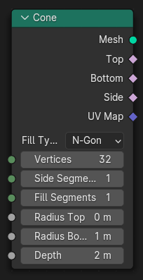
- pynodes.geosocks.MeshCube(size=(1.0, 1.0, 1.0), vertices_x=2, vertices_y=2, vertices_z=2)#
The Cube node generates a cuboid mesh with variable side lengths and subdivisions. The inside of the mesh is still hollow like a normal cube.
Path#
Mesh > Primitives > Cube Node
Outputs:#
#0 mesh: Geometry = None#1 uv_map: Vector = (0.0, 0.0, 0.0)
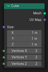
- pynodes.geosocks.MeshCylinder(fill_type='NGON', vertices=32, side_segments=1, fill_segments=1, radius=1.0, depth=2.0)#
The Cylinder node generates a cylinder mesh. It is similar to the Cone node but always uses the same radius for the circles at the top and bottom.
Path#
Mesh > Primitives > Cylinder Node
Properties#
fill_type:NGON,NONE,TRIANGLE_FAN
Outputs:#
#0 mesh: Geometry = None#1 top: Boolean = False#2 side: Boolean = False#3 bottom: Boolean = False#4 uv_map: Vector = (0.0, 0.0, 0.0)
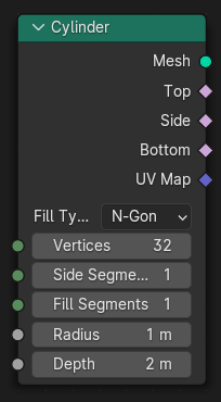
- pynodes.geosocks.MeshGrid(size_x=1.0, size_y=1.0, vertices_x=3, vertices_y=3)#
The Grid node generates a planar mesh on the XY plane.
Path#
Mesh > Primitives > Grid Node
Outputs:#
#0 mesh: Geometry = None#1 uv_map: Vector = (0.0, 0.0, 0.0)
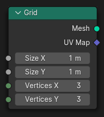
- pynodes.geosocks.MeshIcoSphere(radius=1.0, subdivisions=1)#
The Icosphere node generates a spherical mesh that consists of equally sized triangles.
Path#
Mesh > Primitives > Icosphere Node
Outputs:#
#0 mesh: Geometry = None#1 uv_map: Vector = (0.0, 0.0, 0.0)
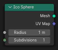
- pynodes.geosocks.MeshCircle(vertices=32, radius=1.0, fill_type='NONE')#
The Mesh Circle node generates a circular ring of edges that is optionally filled with faces.
Path#
Mesh > Primitives > Mesh Circle Node
Properties#
fill_type:NONE,NGON,TRIANGLE_FAN
Outputs:#
#0 mesh: Geometry = None
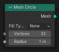
- pynodes.geosocks.MeshCircleFilledNgon(vertices=32, radius=1.0)#
The Mesh Circle node generates a circular ring of edges that is optionally filled with faces.
Path#
Mesh > Primitives > Mesh Circle Node
Properties#
fill_type:NONE,NGON,TRIANGLE_FAN
Outputs:#
#0 mesh: Geometry = None
- pynodes.geosocks.MeshCircleFilledTriangle(vertices=32, radius=1.0)#
The Mesh Circle node generates a circular ring of edges that is optionally filled with faces.
Path#
Mesh > Primitives > Mesh Circle Node
Properties#
fill_type:NONE,NGON,TRIANGLE_FAN
Outputs:#
#0 mesh: Geometry = None
- pynodes.geosocks.MeshLine(start_location=(0.0, 0.0, 0.0), offset=(0.0, 0.0, 1.0), count=10)#
The Mesh Line node generates vertices in a line and connects them with edges.
Path#
Mesh > Primitives > Mesh Line Node
Outputs:#
#0 mesh: Geometry = None
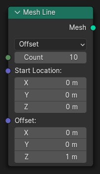
- pynodes.geosocks.MeshLineEndPoints(start_location=(0.0, 0.0, 0.0), end_location=(0.0, 0.0, 1.0), count_mode='TOTAL', count=10, resolution=1.0)#
The Mesh Line node generates vertices in a line and connects them with edges.
Path#
Mesh > Primitives > Mesh Line Node
Properties#
count_mode:TOTAL,RESOLUTION
Outputs:#
#0 mesh: Geometry = None
- pynodes.geosocks.MeshUVSphere(segments=32, rings=16, radius=1.0)#
The UV Sphere node generates a spherical mesh mostly out of quads except for triangles at the top and bottom.
Path#
Mesh > Primitives > UV Sphere Node
Outputs:#
#0 mesh: Geometry = None#1 uv_map: Vector = (0.0, 0.0, 0.0)
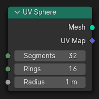
- pynodes.geosocks.InputPoints(count=1, position=(0.0, 0.0, 0.0), radius=0.1)#
The Points node generate a point cloud with positions and radii defined by fields.
Path#
Point > Points Node
Outputs:#
#0 geometry: Geometry = None
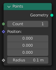
- pynodes.geosocks.VolumeCube(density=1.0, background=0.0, min=(-1.0, -1.0, -1.0), max=(1.0, 1.0, 1.0), resolution_x=32, resolution_y=32, resolution_z=32)#
The Volume Cube generates a volume from scratch by evaluating an input field on every single voxel in a rectangular prism. The Density field defines the output volume grid’s value at every voxel. The field can only depend on the Position Node.
Path#
Volume > Volume Cube Node
Outputs:#
#0 volume: Geometry = None
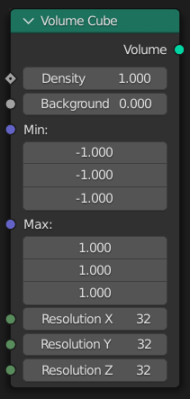
- pynodes.geosocks.join(*items: pynodes.geosocks.Geometry)#
The Join Geometry node merges separately generated geometries into a single one. If the geometry inputs contain different types of data, the output will also contain different data types.
Path#
Geometry > Join Geometry Node
Outputs:#
#0 geometry: Geometry = None
- pynodes.geosocks.join_to_instances(*items: pynodes.geosocks.Geometry)#
The Geometry to Instance node turns every connected input geometry into an instance. Visually, the node has a similar result as the Join Geometry Node, but it outputs the result as separate instances instead. The geometry data itself isn’t actually joined.
Path#
Geometry > Geometry to Instance Node
Outputs:#
#0 instances: Geometry = None
- pynodes.geosocks.SplineParameter()#
The Spline Parameter node outputs how far along each spline a control point is. The Factor output is different from dividing the index by the total number of control points, because the control points might not be equally spaced along the curve.
Path#
Curve > Read > Spline Parameter Node
Outputs:#
#0 factor: Float = 0.0#1 length: Float = 0.0#2 index: Integer = 0