pynodes.datasocks#
Module Contents#
Classes#
Floating-point number socket of a node, float in [-inf, inf], default 0.0 |
|
Floating-point number socket of a node, float in [-inf, inf], default 0.0 |
|
Floating-point number socket of a node, float in [-inf, inf], default 0.0 |
|
Floating-point number socket of a node, float in [0, 1], default 0.0 |
|
Floating-point number socket of a node, float in [-inf, inf], default 0.0 |
|
Floating-point number socket of a node, float in [-inf, inf], default 0.0 |
|
Floating-point number socket of a node, float in [-inf, inf], default 0.0 |
|
Floating-point number socket of a node, float in [0, inf], default 0.0 |
|
3D vector socket of a node, float array of 3 items in [-inf, inf], default (0.0, 0.0, 0.0) |
|
3D vector socket of a node, mathutils.Vector of 3 items in [-inf, inf], default (0.0, 0.0, 0.0) |
|
3D vector socket of a node, mathutils.Vector of 3 items in [-inf, inf], default (0.0, 0.0, 1.0) |
|
3D vector socket of a node, mathutils.Euler rotation of 3 items in [-inf, inf], default (0.0, 0.0, 0.0) |
|
3D vector socket of a node, mathutils.Vector of 3 items in [-inf, inf], default (0.0, 0.0, 0.0) |
|
3D vector socket of a node, mathutils.Vector of 3 items in [-inf, inf], default (0.0, 0.0, 0.0) |
|
3D vector socket of a node, mathutils.Vector of 3 items in [-inf, inf], default (0.0, 0.0, 0.0) |
|
Integer number socket of a node, int in [-inf, inf], default 0 |
|
Integer factor socket of a node, int in [0, inf], default 1 |
|
Integer number socket of a node, int in [0, inf], default 100 |
|
Integer number socket of a node, int in [0, inf], default 0 |
|
Boolean value socket of a node, default False |
|
String socket of a node |
|
RGBA color socket of a node, float array of 4 items in [0, inf], default (0.0, 0.0, 0.0, 0.0) |
|
Shader socket of a node |
|
Object socket of a node |
|
Collection socket of a node |
|
Texture socket of a node |
|
Material socket of a node |
|
Image socket of a node |
Functions#
The Boolean node provides a Boolean value. |
|
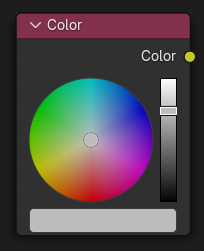
Geometry Nodes Tree: The Color node outputs the color value chosen with the color picker widget. |
|
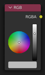
Shader Tree: The RGB node outputs the color value chosen with the color picker widget. |
|
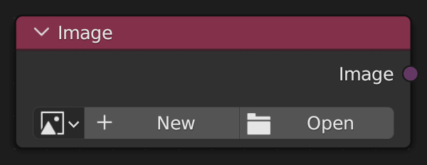
The Image node provides access to a image file which allows you to conveniently enter and switch images for multiple nodes in the tree. |
|
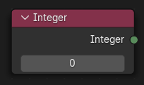
The Integer node provides an integer value. |
|
The Material input node outputs a single material. It can be connected to other material sockets to make using the same material name in multiple places more convenient. |
|
The String input node creates a single string. It can be connected to attribute name sockets to make using the same attribute name in multiple places more convenient. |
|
The String to Curves converts a string to curve instances. Each unique character used in the string is converted to a curve once, and further uses of that character are more instances of the same geometry. |
|
The Value Node is a simple node to input numerical values to other nodes in the tree. |
|
The Value Node is a simple node to input numerical values to other nodes in the tree. |
|
The Vector input node creates a single vector. |
|
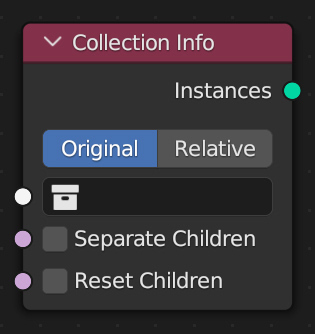
The Collection Info node gets information from collections. This can be useful to control parameters in the geometry node tree with an external collection. |
|
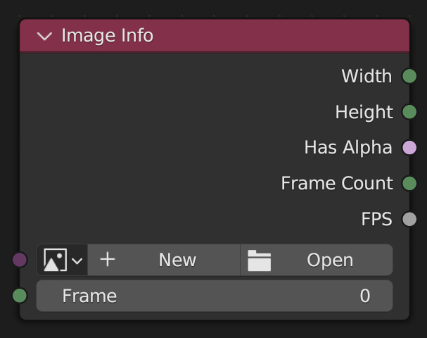
The Image Info node gets information from image and animation. This can be useful to generate parameters in the geometry node for arbitrary images. Image information can be either general or frame-specific. |
|
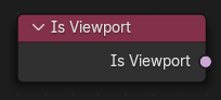
The Is Viewport node outputs true when geometry nodes are evaluated for the viewport. For the final render the node outputs false. |
|
The Object Info node gets information from objects. This can be useful to control parameters in the geometry node tree with an external object, either directly by using its geometry, or via its transformation properties. |
|
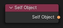
The Self Object node outputs the object that contains the geometry nodes modifier currently being executed. This can be used to retrieve the original transforms. |
|
The Viewer node allows viewing data from inside a geometry node group in the Spreadsheet Editor and the 3D Viewport. |
|
The Viewer node allows viewing data from inside a geometry node group in the Spreadsheet Editor and the 3D Viewport. |
|
The Viewer node allows viewing data from inside a geometry node group in the Spreadsheet Editor and the 3D Viewport. |
|
The Viewer node allows viewing data from inside a geometry node group in the Spreadsheet Editor and the 3D Viewport. |
|
The Viewer node allows viewing data from inside a geometry node group in the Spreadsheet Editor and the 3D Viewport. |
|
The Viewer node allows viewing data from inside a geometry node group in the Spreadsheet Editor and the 3D Viewport. |
|
The Brick Texture is used to add a procedural texture producing bricks. |
|
The Checker Texture is used to add a checkerboard texture. |
|
The Gradient Texture node generates interpolated color and intensity values based on the input vector. |
|
The Image Texture node is used to add an image file as a texture. The image data is sampled with the input Vector and outputs a Color and Alpha value. |
|
The Magic Texture node is used to add a psychedelic color texture. |
|
The Musgrave Texture node evaluates a fractal Perlin noise at the input texture coordinates. Unlike the Noise Texture, which is also a fractal Perlin noise, the Musgrave Texture allows greater control over how octaves are combined. |
|
The Noise Texture node evaluates a fractal Perlin noise at the input texture coordinates. |
|
The Voronoi Texture node evaluates a Worley Noise at the input texture coordinates. |
|
The Wave Texture node adds procedural bands or rings with noise distortion. |
|
The Wave Texture node adds procedural bands or rings with noise distortion. |
|
The Wave Texture node adds procedural bands or rings with noise distortion. |
|
The White Noise Texture node returns a random number based on an input Seed. The seed can be a number, a 2D vector, a 3D vector, or a 4D vector; depending on the Dimensions property. The output number ranges between zero and one. |
|
The Color Ramp Node is used for mapping values to colors with the use of a gradient. |
|
The Combine Color Node combines an image from its composite color channels. The node can combine multiple Color Models depending on the Mode property. |
|
The Combine Color Node combines an image from its composite color channels. The node can combine multiple Color Models depending on the Mode property. |
|
The Combine Color Node combines an image from its composite color channels. The node can combine multiple Color Models depending on the Mode property. |
|
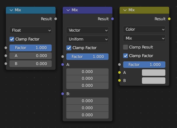
The Mix Node mixes values, colors and vectors inputs using a factor to control the amount of interpolation. The Color mode has additional blending modes. |
|
The Mix Node mixes images by working on the individual and corresponding pixels of the two input images. Called “Mix Color” in the shader, geometry, and texture context. |
|
The Mix Node mixes images by working on the individual and corresponding pixels of the two input images. Called “Mix Color” in the shader, geometry, and texture context. |
|
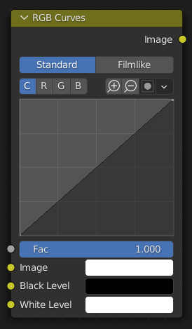
The RGB Curves Node allows color corrections for each color channel and levels adjustments in the compositing context. |
|
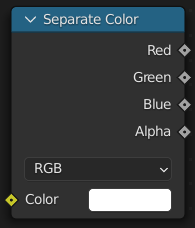
The Separate Color Node splits an image into its composite color channels. The node can output multiple Color Models depending on the Mode property. |
|
The Combine XYZ Node combines a vector from its individual components. |
|
The Math Node performs math operations. |
|
The Vector Math node performs the selected math operation on the input vectors. |
|
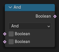
The Boolean Math node performs a basic logical operation on its inputs. |
|
The Compare node takes two inputs and does an operation to determine whether they are similar. The node can work on all generic data types, and has modes for vectors that contain more complex comparisons, which can help to reduce the number of necessary nodes, and make a node tree more readable. |
|
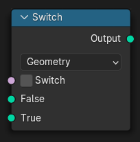
The Switch node outputs one of two inputs depending on a condition. Only the input that is passed through the node is computed. |
|
The Random Value node outputs a white noise like value as a Float, Integer, Vector, or Boolean field. |
|
The Random Value node outputs a white noise like value as a Float, Integer, Vector, or Boolean field. |
|
The Random Value node outputs a white noise like value as a Float, Integer, Vector, or Boolean field. |
|
The Random Value node outputs a white noise like value as a Float, Integer, Vector, or Boolean field. |
|
The Position node outputs a vector of each point of the geometry the node is connected to. |
|
The Index node gives an integer value indicating the position of each element in the list, starting at zero. This depends on the internal order of the data in the geometry, which is not necessarily visible in the 3D Viewport. However, the index value is visible in the left-most column in the Spreadsheet Editor. |
|
The Scene Time node outputs the current time in the scene’s animation in units of seconds or frames. |
|
The Ambient Occlusion shader computes how much the hemisphere above the shading point is occluded. This can be used for procedural texturing, for example to add weathering effects to corners only. |
|
The Node Environmental Texture is used to light your scene using an environment map image file as a texture. |
|
The IES Texture is used to match real world lights based on IES files (IES). IES files store the directional intensity distribution of light sources. |
|
The Image Texture is used to add an image file as a texture. |
|
The Point Density node is used to add volumetric points for each particle or vertex of another object. |
|
The Sky Texture node adds a procedural Sky texture. |
|
ShaderNodeBrightContrast |
|
Use this node to apply a gamma correction. |
|
The Hue Saturation Value Node applies a color transformation in the HSV Color Model. |
|
Cycles Only |
|
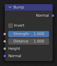
The Bump node generates a perturbed normal from a height texture, for bump mapping. The height value will be sampled at the shading point and two nearby points on the surface to determine the local direction of the normal. |
|
The Displacement node is used to displace the surface along the surface normal, to add more detail to the geometry. Both procedural textures and baked displacement maps can be used. |
|
The Normal node generates a normal vector and a dot product. |
|
The Normal Map node generates a perturbed normal from an RGB normal map image. This is usually chained with an Image Texture node in the color input, to specify the normal map image. For tangent space normal maps, the UV coordinates for the image must match, and the image texture should be set to Non-Color mode to give correct results. |
|
The Vector Displacement node is used to displace the surface along arbitrary directions, unlike the regular Displacement node which only displaces along the surface normal. |
|
The Vector Transform node allows converting a vector, point, or normal between world and camera and object coordinate space. |
|
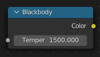
The Blackbody node converts a blackbody temperature to RGB value. This can be useful for materials that emit light at natural occurring frequencies. |
|
The Combine Color Node combines an image from its composite color channels. The node can combine multiple Color Models depending on the Mode property. |
|
The RGB to BW Node maps an RGB color image to a gray-scale by the luminance. |
|
The Separate Color Node splits an image into its composite color channels. The node can output multiple Color Models depending on the Mode property. |
|
The Wavelength node converts a wavelength value to an RGB value. This can be used to achieve a specific color on the light spectrum. |
|
The Texture Coordinate node is commonly used for the coordinates of textures, typically used as inputs for the Vector input for texture nodes. |
|
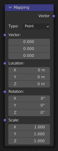
The Mapping node transforms the input vector by applying translation, rotation, and scaling. |
|
The Geometry node gives geometric information about the current shading point. All vector coordinates are in World Space. For volume shaders, only the position and incoming vector are available. |
|
The Mix node is used to mix two shaders together. Mixing can be used for material layering, where the Factor input may, for example, be connected to a Blend Weight node. |
|
It is also possible to create your own nodes using Open Shading Language (OSL). These nodes will only work with the CPU and OptiX rendering backend. OSL was designed for node-based shading, and each OSL shader corresponds to one node in a node setup. To add an OSL shader, add a script node and link it to a text data-block or an external file. Input and output sockets will be created from the shader parameters on clicking the update button in the Node or the Text editor. OSL shaders can be linked to the node in a few different ways. With the Internal mode, a text data-block is used to store the OSL shader, and the OSO bytecode is stored in the node itself. This is useful for distributing a blend-file with everything packed into it. The External mode can be used to specify a |
|
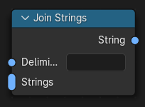
The Join Strings node combines any number of input strings into the output string. The order of the result depends on the vertical ordering of the inputs in the multi-input socket. |
|
The Attribute node allows you to retrieve attributes attached to an object or mesh. |
Data#
API#
- pynodes.datasocks.is_4_0_beta_or_higher = None#
- class pynodes.datasocks.Float(bsocket: bpy.types.NodeSocket)#
Bases:
pynodes.core.SocketFloating-point number socket of a node, float in [-inf, inf], default 0.0
Initialization
- bl_idname = 'NodeSocketFloat'#
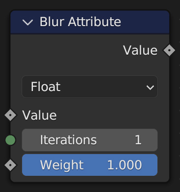
- blur(iterations=1, weight=1.0)#
The Blur Attribute node smooths attribute values between neighboring geometry elements.
Path#
Attribute > Blur Attribute Node
Outputs:#
#0 value_float: Float = 0.0
- switch(switch=False, true_float=True)#
The Switch node outputs one of two inputs depending on a condition. Only the input that is passed through the node is computed.
Path#
Utilities > Switch Node
Outputs:#
#0 output: Float = 0.0
- mix(b_float=0.0, factor_float=0.5, clamp_factor=True)#
The Mix Node mixes values, colors and vectors inputs using a factor to control the amount of interpolation. The Color mode has additional blending modes.
Path#
Utilities > Math > Mix Node
Outputs:#
#0 result_float: Float = 0.0
- color_ramp(start_color=(0.0, 0.0, 0.0, 1.0), end_color=(1.0, 1.0, 1.0, 1.0), color_mode=None, interpolation=None)#
The Color Ramp Node is used for mapping values to colors with the use of a gradient.
Item of colors: hex string or float or tuple
color_mode:RGB,HSV,HSLinterpolation:EASE,CARDINAL,LINEAR,B_SPLINE,CONSTANTinterpolation(HSV):NEAR,FAR,CW,CCW
Path#
Utilities > Color > Color Ramp Node
Outputs:#
#0 color: Color = (0.0, 0.0, 0.0, 0.0)#1 alpha: Float = 0.0
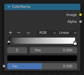
- color_ramp_uniform(*colors, interpolation=None)#
The Color Ramp Node is used for mapping values to colors with the use of a gradient.
Item of colors: hex string or float or tuple
interpolation:EASE,CARDINAL,LINEAR,B_SPLINE,CONSTANT
Path#
Utilities > Color > Color Ramp Node
Outputs:#
#0 color: Color = (0.0, 0.0, 0.0, 0.0)#1 alpha: Float = 0.0
- color_ramp_with_position(*colors: tuple, interpolation=None)#
The Color Ramp Node is used for mapping values to colors with the use of a gradient.
colors:[(position, color), ...]position from 0 to 1, color: hex string or float or tupleinterpolation:EASE,CARDINAL,LINEAR,B_SPLINE,CONSTANT
Path#
Utilities > Color > Color Ramp Node
Outputs:#
#0 color: Color = (0.0, 0.0, 0.0, 0.0)#1 alpha: Float = 0.0
- to_normal(invert=False, strength=1.0, distance=1.0, normal=(0.0, 0.0, 0.0))#
The Bump node generates a perturbed normal from a height texture, for bump mapping. The height value will be sampled at the shading point and two nearby points on the surface to determine the local direction of the normal.
Path#
Vector > Bump Node
Outputs:#
#0 normal: Vector = (0.0, 0.0, 0.0)
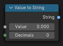
- to_string(decimals=0)#
The Value to String node generates string representation of the input value.
Path#
Utilities > Text > Value to String Node
Outputs:#
#0 string: String = ""
- to_blackbody()#
The Blackbody node converts a blackbody temperature to RGB value. This can be useful for materials that emit light at natural occurring frequencies.
Path#
Converter > Blackbody Node
Outputs:#
#0 color: Color = (0.0, 0.0, 0.0, 0.0)
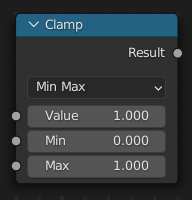
- clamp(clamp_type='MINMAX', min=0.0, max=1.0)#
The Clamp node clamps a value between a minimum and a maximum.
Path#
Utilities > Math > Clamp Node
Properties:#
clamp_type:MINMAX,RANGE
Outputs:#
#0 result: Float = 0.0
- float_curve(factor=1.0, points: list[tuple[float, float, str]] = None)#
The Float Curve node maps an input float to a curve and outputs a float value.
points:[(posx, posy, 'handle_type'), ...]handle_type[Optional]:AUTO,AUTO_CLAMPED,VECTORExample:
value.float_curve(points=[(0, 0), (0.05, 0.03), (0.5, 0.5, "AUTO_CLAMPED"), (1, 0.5)])
Path#
Utilities > Math > Float Curve
Outputs:#
#0 value: Float = 0.0
- classmethod curve(value=1.0, factor=1.0, points: list[tuple[float, float]] = None)#
The Float Curve node maps an input float to a curve and outputs a float value.
Path#
Utilities > Math > Float Curve
Outputs:#
#0 value: Float = 0.0
- to_integer(rounding_mode='ROUND')#
The Float To Integer node takes a single floating point number input and converts it to an integer with a choice of methods.
Path#
Utilities > Math > Float To Integer Node
Properties:#
rounding_mode:ROUND,FLOOR,CEILING,TRUNCATE
Outputs:#
#0 integer: Integer = 0
- map_range(from_min=0.0, from_max=1.0, to_min=0.0, to_max=1.0, interpolation_type='LINEAR', steps=4.0, clamp=True)#
The Map Range node remaps a value from a range to a target range.
Path#
Utilities > Math > Map Range Node
Properties:#
interpolation_type:LINEAR,STEPPED,SMOOTHSTEP,SMOOTHERSTEP
Outputs:#
#0 result: Float = 0.0
- math(operation='ADD', value_001=0.5, value_002=0.5, use_clamp=False)#
The Math Node performs math operations.
Path#
Utilities > Math > Math Node
Properties:#
operation:ADD,SUBTRACT,MULTIPLY,DIVIDE,MULTIPLY_ADD,POWER,LOGARITHM,SQRT,INVERSE_SQRT,ABSOLUTE,EXPONENT,MINIMUM,MAXIMUM,LESS_THAN,GREATER_THAN,SIGN,COMPARE,SMOOTH_MIN,SMOOTH_MAX,ROUND,FLOOR,CEIL,TRUNC,FRACT,MODULO,WRAP,SNAP,PINGPONG,SINE,COSINE,TANGENT,ARCSINE,ARCCOSINE,ARCTANGENT,ARCTAN2,SINH,COSH,TANH,RADIANS,DEGREES
Outputs:#
#0 value: Float = 0.0
- __neg__()#
- __add__(other)#
- __radd__(other)#
- __sub__(other)#
- __rsub__(other)#
- __mul__(other)#
- __rmul__(other)#
- __truediv__(other)#
- __rtruediv__(other)#
- __floordiv__(other)#
- __rfloordiv__(other)#
- __eq__(other)#
- __ne__(other)#
- __ge__(other)#
- __gt__(other)#
- __le__(other)#
- __lt__(other)#
- multiply_add(multiplier=0.5, addend=0.5, clamp=False)#
The sum of the product of the two values with Addend.
Path#
Utilities > Math > Math Node
- power(exponent=0.5, clamp=False)#
The Base raised to the power of Exponent.
Path#
Utilities > Math > Math Node
- __pow__(exponent)#
- __rpow__(base)#
- log(base=0.5, clamp=False)#
The log of the value with a Base as its base.
Path#
Utilities > Math > Math Node
- property inverse_sqrt#
One divided by the square root of the value.
Path#
Utilities > Math > Math Node
- classmethod sqrt(value=0.5, clamp=False)#
The square root of the value.
Path#
Utilities > Math > Math Node
- property absolute#
Equivalent to built-in function
abs(self). The input value is read without regard to its sign. This turns negative values into positive values.Path#
Utilities > Math > Math Node
- __abs__()#
- property exponent#
Raises Euler’s number to the power of the value.
Path#
Utilities > Math > Math Node
- classmethod exp(value)#
- minimum(other=0.5, clamp=False)#
Outputs the smallest of the input values.
Path#
Utilities > Math > Math Node
- maximum(other=0.5, clamp=False)#
Outputs the largest of two input values.
Path#
Utilities > Math > Math Node
- less_than(threshold=0.5, clamp=False)#
Outputs 1.0 if the first value is smaller than the second value. Otherwise the output is 0.0.
Path#
Utilities > Math > Math Node
- greater_than(threshold=0.5, clamp=False)#
Outputs 1.0 if the first value is larger than the second value. Otherwise the output is 0.0.
Path#
Utilities > Math > Math Node
- property sign#
Extracts the sign of the input value. All positive numbers will output 1.0. All negative numbers will output -1.0. And 0.0 will output 0.0.
Path#
Utilities > Math > Math Node
- compare(other=0.5, epsilon=0.5, clamp=False)#
Outputs 1.0 if the difference between the two input values is less than or equal to Epsilon.
Path#
Utilities > Math > Math Node
- __round__()#
To get called by built-in round() function.
- property floor#
Rounds the input value down to the nearest integer.
Path#
Utilities > Math > Math Node
- __floor__()#
To get called by built-in math.floor() function.
- __ceil__()#
To get called by built-in math.ceil() function.
- __trunc__()#
To get called by built-in math.trunc() function.
- modulo(other=0.5, clamp=False)#
Outputs the remainder once the first value is divided by the second value.
Path#
Utilities > Math > Math Node
- __mod__(other)#
To get called on modulo operation using % operator.
- wrap(max=0.5, min=0.5, clamp=False)#
Outputs a value between Min and Max based on the absolute difference between the input value and the nearest integer multiple of Max less than the value.
Path#
Utilities > Math > Math Node
- snap(increment=0.5, clamp=False)#
Rounds the input value down to the nearest integer multiple of Increment.
Path#
Utilities > Math > Math Node
- pingpong(scale=0.5, clamp=False)#
The output value is moved between 0.0 and the Scale based on the input value.
Path#
Utilities > Math > Math Node
- classmethod sin(value=0.5, clamp=False)#
The Sine of the input value.
Path#
Utilities > Math > Math Node
- classmethod cos(value=0.5, clamp=False)#
The Cosine of the input value.
Path#
Utilities > Math > Math Node
- classmethod tan(value=0.5, clamp=False)#
The Tangent of the input value.
Path#
Utilities > Math > Math Node
- classmethod arcsin(value=0.5, clamp=False)#
The ArcSine of the input value.
Path#
Utilities > Math > Math Node
- classmethod arccos(value=0.5, clamp=False)#
The ArcCosine of the input value.
Path#
Utilities > Math > Math Node
- property arctangent#
The ArcTangent of the input value.
Path#
Utilities > Math > Math Node
- classmethod arctan(value=0.5, clamp=False)#
The ArcTangent of the input value.
Path#
Utilities > Math > Math Node
- arctan2(other=0.5, clamp=False)#
Outputs the Inverse Tangent of the first value divided by the second value measured in radians.
Path#
Utilities > Math > Math Node
- property hyperbolic_sine#
The Hyperbolic Sine of the input value.
Path#
Utilities > Math > Math Node
- classmethod sinh(value=0.5, clamp=False)#
The Hyperbolic Sine of the input value.
Path#
Utilities > Math > Math Node
- property hyperbolic_cosine#
The Hyperbolic Cosine of the input value.
Path#
Utilities > Math > Math Node
- classmethod cosh(value=0.5, clamp=False)#
The Hyperbolic Cosine of the input value.
Path#
Utilities > Math > Math Node
- property hyperbolic_tangent#
The Hyperbolic Tangent of the input value.
Path#
Utilities > Math > Math Node
- classmethod tanh(value=0.5, clamp=False)#
The Hyperbolic Tangent of the input value.
Path#
Utilities > Math > Math Node
- class pynodes.datasocks.Angle(bsocket: bpy.types.NodeSocket)#
Bases:
pynodes.datasocks.FloatFloating-point number socket of a node, float in [-inf, inf], default 0.0
Initialization
- bl_idname = 'NodeSocketFloatAngle'#
- class pynodes.datasocks.Distance(bsocket: bpy.types.NodeSocket)#
Bases:
pynodes.datasocks.FloatFloating-point number socket of a node, float in [-inf, inf], default 0.0
Initialization
- bl_idname = 'NodeSocketFloatDistance'#
- class pynodes.datasocks.Factor(bsocket: bpy.types.NodeSocket)#
Bases:
pynodes.datasocks.FloatFloating-point number socket of a node, float in [0, 1], default 0.0
Initialization
- bl_idname = 'NodeSocketFloatFactor'#
- class pynodes.datasocks.Percentage(bsocket: bpy.types.NodeSocket)#
Bases:
pynodes.datasocks.FloatFloating-point number socket of a node, float in [-inf, inf], default 0.0
Initialization
- bl_idname = 'NodeSocketFloatPercentage'#
- class pynodes.datasocks.FloatTime(bsocket: bpy.types.NodeSocket)#
Bases:
pynodes.datasocks.FloatFloating-point number socket of a node, float in [-inf, inf], default 0.0
Initialization
- bl_idname = 'NodeSocketFloatTime'#
- class pynodes.datasocks.FloatTimeAbsolute(bsocket: bpy.types.NodeSocket)#
Bases:
pynodes.datasocks.FloatFloating-point number socket of a node, float in [-inf, inf], default 0.0
Initialization
- bl_idname = 'NodeSocketFloatTimeAbsolute'#
- class pynodes.datasocks.Unsigned(bsocket: bpy.types.NodeSocket)#
Bases:
pynodes.datasocks.FloatFloating-point number socket of a node, float in [0, inf], default 0.0
Initialization
- bl_idname = 'NodeSocketFloatUnsigned'#
- class pynodes.datasocks.Vector(bsocket: bpy.types.NodeSocket)#
Bases:
pynodes.core.Socket3D vector socket of a node, float array of 3 items in [-inf, inf], default (0.0, 0.0, 0.0)
Initialization
- bl_idname = 'NodeSocketVector'#
- property x#
- property y#
- property z#
- property separated#
- property xyz#
- __eq__(other)#
- __ne__(other)#
- line_to(end=(0.0, 0.0, 1.0))#
The Curve Line node generates poly spline line.
Path#
Curve > Primitives > Curve Line Node
Outputs:#
#0 curve: Geometry = None
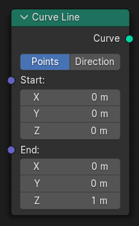
- line_towards(direction=(0.0, 0.0, 1.0), length=1.0)#
The Curve Line node generates poly spline line.
Path#
Curve > Primitives > Curve Line Node
Outputs:#
#0 curve: Geometry = None
- blur(iterations=1, weight=1.0)#
The Blur Attribute node smooths attribute values between neighboring geometry elements.
Path#
Attribute > Blur Attribute Node
Outputs:#
#2 value_vector: Vector = (0.0, 0.0, 0.0)
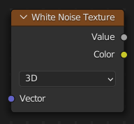
- to_white_noise(noise_dimensions='3D', w=0.0)#
The White Noise Texture node returns a random number based on an input Seed. The seed can be a number, a 2D vector, a 3D vector, or a 4D vector; depending on the Dimensions property. The output number ranges between zero and one.
Path#
Texture > White Noise Texture Node
Properties:#
noise_dimensions:3D,1D,2D,4D
Outputs:#
#0 value: Float = 0.0#1 color: Color = (0.0, 0.0, 0.0, 0.0)
- switch(switch=False, true_vector=(0.0, 0.0, 0.0))#
The Switch node outputs one of two inputs depending on a condition. Only the input that is passed through the node is computed.
Path#
Utilities > Switch Node
Outputs:#
#3 output: Vector = (0.0, 0.0, 0.0)
- mix(b_vector=(0.0, 0.0, 0.0), factor_float=0.5, factor_vector=(0.5, 0.5, 0.5), factor_mode='UNIFORM', clamp_factor=True)#
The Mix Node mixes values, colors and vectors inputs using a factor to control the amount of interpolation. The Color mode has additional blending modes.
Path#
Utilities > Vector > Mix Node
Outputs:#
#1 result_vector: Vector = (0.0, 0.0, 0.0)
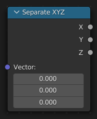
- separate_xyz()#
The Separate XYZ Node splits a vector into its individual components.
Path#
Utilities > Vector > Separate XYZ Node
Outputs:#
#0 x: Float = 0.0#1 y: Float = 0.0#2 z: Float = 0.0
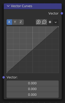
- vector_curve(mapping: bpy.types.CurveMapping = None, fac=1.0)#
The Vector Curves node maps an input vector components to a curve.
Path#
Utilities > Vector > Vector Curves Node
Outputs:#
#0 vector: Vector = (0.0, 0.0, 0.0)
- rotate(rotation_type='AXIS_ANGLE', invert=False, center=(0.0, 0.0, 0.0), axis=(0.0, 0.0, 1.0), angle=math.radians(0.0), rotation=(0.0, 0.0, 0.0))#
The Vector Rotate Node provides the ability to rotate a vector around a pivot point (Center).
Path#
Utilities > Vector > Vector Rotate Node
Properties:#
rotation_type:AXIS_ANGLE,X_AXIS,Y_AXIS,Z_AXIS,EULER_XYZ
Outputs:#
#0 vector: Vector = (0.0, 0.0, 0.0)
- rotate_around_axis(center=(0.0, 0.0, 0.0), axis=(0.0, 0.0, 1.0), angle=math.radians(0.0), invert=False)#
The Vector Rotate Node provides the ability to rotate a vector around a pivot point (Center).
Path#
Utilities > Vector > Vector Rotate Node
Outputs:#
#0 vector: Vector = (0.0, 0.0, 0.0)
- rotate_around_x_axis(center=(0.0, 0.0, 0.0), angle=math.radians(0.0), invert=False)#
The Vector Rotate Node provides the ability to rotate a vector around a pivot point (Center).
Path#
Utilities > Vector > Vector Rotate Node
Outputs:#
#0 vector: Vector = (0.0, 0.0, 0.0)
- rotate_around_y_axis(center=(0.0, 0.0, 0.0), angle=math.radians(0.0), invert=False)#
The Vector Rotate Node provides the ability to rotate a vector around a pivot point (Center).
Path#
Utilities > Vector > Vector Rotate Node
Outputs:#
#0 vector: Vector = (0.0, 0.0, 0.0)
- rotate_around_z_axis(center=(0.0, 0.0, 0.0), angle=math.radians(0.0), invert=False)#
The Vector Rotate Node provides the ability to rotate a vector around a pivot point (Center).
Path#
Utilities > Vector > Vector Rotate Node
Outputs:#
#0 vector: Vector = (0.0, 0.0, 0.0)
- rotate_around_euler_xyz(center=(0.0, 0.0, 0.0), rotation=(0.0, 0.0, 0.0), invert=False)#
The Vector Rotate Node provides the ability to rotate a vector around a pivot point (Center).
Path#
Utilities > Vector > Vector Rotate Node
Outputs:#
#0 vector: Vector = (0.0, 0.0, 0.0)
- rotate_object_euler(rotate_by=(0.0, 0.0, 0.0))#
The Rotate Euler node rotates an Euler rotation.
Path#
Utilities > Rotation > Rotate Euler Node
Outputs:#
#0 rotation: Vector = (0.0, 0.0, 0.0)
- rotate_local_euler(rotate_by=(0.0, 0.0, 0.0))#
The Rotate Euler node rotates an Euler rotation.
Path#
Utilities > Rotation > Rotate Euler Node
Outputs:#
#0 rotation: Vector = (0.0, 0.0, 0.0)
- rotate_object_around_axis_by_angle(axis=(0.0, 0.0, 1.0), angle=math.radians(0.0))#
Use separate axis and angle inputs to control the rotation.
Path#
Utilities > Rotation > Rotate Euler Node
Outputs:#
#0 rotation: Vector = (0.0, 0.0, 0.0)
- rotate_local_around_axis_by_angle(axis=(0.0, 0.0, 1.0), angle=math.radians(0.0))#
Use separate axis and angle inputs to control the rotation.
Path#
Utilities > Rotation > Rotate Euler Node
Outputs:#
#0 rotation: Vector = (0.0, 0.0, 0.0)
- math(operation='ADD', vector_001=(0.0, 0.0, 0.0), vector_002=(0.0, 0.0, 0.0), scale=1.0)#
The Vector Math node performs the selected math operation on the input vectors.
Path#
Utilities > Vector > Vector Math Node
Properties:#
operation:ADD,SUBTRACT,MULTIPLY,DIVIDE,MULTIPLY_ADD,CROSS_PRODUCT,PROJECT,REFLECT,REFRACT,FACEFORWARD,DOT_PRODUCT,DISTANCE,LENGTH,SCALE,NORMALIZE,ABSOLUTE,MINIMUM,MAXIMUM,FLOOR,CEIL,FRACTION,MODULO,WRAP,SNAP,SINE,COSINE,TANGENT
Outputs:#
#0 vector: Vector = (0.0, 0.0, 0.0)#1 value: Float = 0.0
- __add__(other)#
The sum of A and B.
- __radd__(other)#
- __sub__(other)#
The difference between A and B.
- __rsub__(other)#
- __neg__()#
- __mul__(other)#
1.The result of multiplying A by the scalar input Scale; 2.The entrywise product of A and B.
- __rmul__(other)#
1.The result of multiplying A by the scalar input Scale; 2.The entrywise product of A and B.
- __truediv__(other)#
1.The result of multiplying A by the 1/scalar input Scale; 2.The entrywise division of A by B. Division by zero results in zero.
- __rtruediv__(other)#
- multiply_add(multiplier=(0.0, 0.0, 0.0), addend=(0.0, 0.0, 0.0))#
The entrywise combination of the multiply and addition operations. [Manual] [API]
Path#
Utilities > Vector > Vector Math Node
Outputs:#
#0 vector: Vector = (0.0, 0.0, 0.0)
- cross(other=(0.0, 0.0, 0.0))#
The cross product of A and B. [Manual] [API]
Path#
Utilities > Vector > Vector Math Node
Outputs:#
#0 vector: Vector = (0.0, 0.0, 0.0)
- project(other=(0.0, 0.0, 0.0))#
The projection of A onto B. [Manual] [API]
Path#
Utilities > Vector > Vector Math Node
Outputs:#
#0 vector: Vector = (0.0, 0.0, 0.0)
- reflect(other=(0.0, 0.0, 0.0))#
The reflection of A around the normal B. B need not be normalized. [Manual] [API]
Path#
Utilities > Vector > Vector Math Node
Outputs:#
#0 vector: Vector = (0.0, 0.0, 0.0)
- refract(normal=(0.0, 0.0, 0.0), IOR=1.0)#
For a given incident vector A, surface normal B and ratio of indices of refraction (IOR), refract outputs the refraction vector R. [Manual] [API]
Path#
Utilities > Vector > Vector Math Node
Outputs:#
#0 vector: Vector = (0.0, 0.0, 0.0)
- faceforward(b=(0.0, 0.0, 0.0), c=(0.0, 0.0, 0.0))#
Orients a vector A to point away from a surface B as defined by its normal C.
(dot(B, C) < 0) ? A : -A[Manual] [API]Path#
Utilities > Vector > Vector Math Node
Outputs:#
#0 vector: Vector = (0.0, 0.0, 0.0)
- dot(other=(0.0, 0.0, 0.0))#
The dot product of A and B.
A_x · B_x + A_y · B_y + A_z · B_z[Manual] [API]Path#
Utilities > Vector > Vector Math Node
Outputs:#
#1 value: Float = 0.0
- distance(other=(0.0, 0.0, 0.0))#
The distance between A and B. [Manual] [API]
Path#
Utilities > Vector > Vector Math Node
Outputs:#
#1 value: Float = 0.0
- property length#
The length of A. [Manual] [API]
Path#
Utilities > Vector > Vector Math Node
Outputs:#
#1 value: Float = 0.0
- scale(scale=1.0)#
The result of multiplying A by the scalar input Scale. [Manual] [API]
Path#
Utilities > Vector > Vector Math Node
Outputs:#
#0 vector: Vector = (0.0, 0.0, 0.0)
- property normalized#
The result of normalizing A. The result vector points to the same direction as A and has a length of 1. If A is (0, 0, 0), the result is (0, 0, 0) as well. [Manual] [API]
Path#
Utilities > Vector > Vector Math Node
Outputs:#
#0 vector: Vector = (0.0, 0.0, 0.0)
- property absolute#
The entrywise absolute value of A. [Manual] [API]
Path#
Utilities > Vector > Vector Math Node
Outputs:#
#0 vector: Vector = (0.0, 0.0, 0.0)
- __abs__()#
- minimum(other=(0.0, 0.0, 0.0))#
The entrywise minimum value from A and B. [Manual] [API]
Path#
Utilities > Vector > Vector Math Node
Outputs:#
#0 vector: Vector = (0.0, 0.0, 0.0)
- maximum(other=(0.0, 0.0, 0.0))#
The entrywise maximum value from A and B. [Manual] [API]
Path#
Utilities > Vector > Vector Math Node
Outputs:#
#0 vector: Vector = (0.0, 0.0, 0.0)
- floor()#
Rounds the input value entrywise down to the nearest integer. [Manual] [API]
Path#
Utilities > Vector > Vector Math Node
Outputs:#
#0 vector: Vector = (0.0, 0.0, 0.0)
- __floor__()#
- ceil()#
Rounds the input value entrywise up to the nearest integer. [Manual] [API]
Path#
Utilities > Vector > Vector Math Node
Outputs:#
#0 vector: Vector = (0.0, 0.0, 0.0)
- __ceil__()#
- fraction()#
Returns the fractional part of the value entrywise. [Manual] [API]
Path#
Utilities > Vector > Vector Math Node
Outputs:#
#0 vector: Vector = (0.0, 0.0, 0.0)
- property fract#
Returns the fractional part of the value entrywise. [Manual] [API]
Path#
Utilities > Vector > Vector Math Node
Outputs:#
#0 vector: Vector = (0.0, 0.0, 0.0)
- modulo(other=(0.0, 0.0, 0.0))#
The entrywise modulo of A by B. [Manual] [API]
Path#
Utilities > Vector > Vector Math Node
Outputs:#
#0 vector: Vector = (0.0, 0.0, 0.0)
- __mod__(other)#
- wrap(max=(0.0, 0.0, 0.0), min=(0.0, 0.0, 0.0))#
The entrywise output of a value between Min and Max based on the absolute difference between the input value and the nearest integer multiple of Max less than the value. [Manual] [API]
Path#
Utilities > Vector > Vector Math Node
Outputs:#
#0 vector: Vector = (0.0, 0.0, 0.0)
- snap(increment=(0.0, 0.0, 0.0))#
The result of rounding A to the largest integer multiple of B less than or equal A. [Manual] [API]
Path#
Utilities > Vector > Vector Math Node
Outputs:#
#0 vector: Vector = (0.0, 0.0, 0.0)
- sin()#
The entrywise Sine of A. [Manual] [API]
Path#
Utilities > Vector > Vector Math Node
Outputs:#
#0 vector: Vector = (0.0, 0.0, 0.0)
- cos()#
The entrywise Cosine of A. [Manual] [API]
Path#
Utilities > Vector > Vector Math Node
Outputs:#
#0 vector: Vector = (0.0, 0.0, 0.0)
- tangent()#
The entrywise Tangent of A. [Manual] [API]
Path#
Utilities > Vector > Vector Math Node
Outputs:#
#0 vector: Vector = (0.0, 0.0, 0.0)
- map_range(from_min=(0.0, 0.0, 0.0), from_max=(1.0, 1.0, 1.0), to_min=(0.0, 0.0, 0.0), to_max=(1.0, 1.0, 1.0), interpolation_type='LINEAR', clamp=True, steps=(4.0, 4.0, 4.0))#
The Map Range node remaps a value from a range to a target range.
Path#
Utilities > Math > Map Range Node
Properties:#
interpolation_type:LINEAR,STEPPED,SMOOTHSTEP,SMOOTHERSTEP
Outputs:#
#1 vector: Vector = (0.0, 0.0, 0.0)
- align_euler_to_vector(axis='X', pivot_axis='AUTO', rotation=(0.0, 0.0, 0.0), factor=1.0)#
The Align Euler to Vector node rotates an Euler rotation into the given direction.
Path#
Utilities > Rotation > Align Euler to Vector Node
Properties:#
axis:X,Y,Zpivot_axis:AUTO,X,Y,Z
Outputs:#
#0 rotation: Vector = (0.0, 0.0, 0.0)
- mapping(vector_type='POINT', location=(0.0, 0.0, 0.0), rotation=(0.0, 0.0, 0.0), scale=(1.0, 1.0, 1.0))#
The Mapping node transforms the input vector by applying translation, rotation, and scaling.
Path#
Vector > Mapping Node
Properties:#
vector_type:POINT,TEXTURE,VECTOR,NORMAL
Outputs:#
#0 vector: Vector = (0.0, 0.0, 0.0)
- class pynodes.datasocks.VectorAcceleration(bsocket: bpy.types.NodeSocket)#
Bases:
pynodes.datasocks.Vector3D vector socket of a node, mathutils.Vector of 3 items in [-inf, inf], default (0.0, 0.0, 0.0)
Initialization
- bl_idname = 'NodeSocketVectorAcceleration'#
- class pynodes.datasocks.VectorDirection(bsocket: bpy.types.NodeSocket)#
Bases:
pynodes.datasocks.Vector3D vector socket of a node, mathutils.Vector of 3 items in [-inf, inf], default (0.0, 0.0, 1.0)
Initialization
- bl_idname = 'NodeSocketVectorDirection'#
- class pynodes.datasocks.VectorEuler(bsocket: bpy.types.NodeSocket)#
Bases:
pynodes.datasocks.Vector3D vector socket of a node, mathutils.Euler rotation of 3 items in [-inf, inf], default (0.0, 0.0, 0.0)
Initialization
- bl_idname = 'NodeSocketVectorEuler'#
- class pynodes.datasocks.VectorTranslation(bsocket: bpy.types.NodeSocket)#
Bases:
pynodes.datasocks.Vector3D vector socket of a node, mathutils.Vector of 3 items in [-inf, inf], default (0.0, 0.0, 0.0)
Initialization
- bl_idname = 'NodeSocketVectorTranslation'#
- class pynodes.datasocks.VectorVelocity(bsocket: bpy.types.NodeSocket)#
Bases:
pynodes.datasocks.Vector3D vector socket of a node, mathutils.Vector of 3 items in [-inf, inf], default (0.0, 0.0, 0.0)
Initialization
- bl_idname = 'NodeSocketVectorVelocity'#
- class pynodes.datasocks.VectorXYZ(bsocket: bpy.types.NodeSocket)#
Bases:
pynodes.datasocks.Vector3D vector socket of a node, mathutils.Vector of 3 items in [-inf, inf], default (0.0, 0.0, 0.0)
Initialization
- bl_idname = 'NodeSocketVectorXYZ'#
- class pynodes.datasocks.Integer(bsocket: bpy.types.NodeSocket)#
Bases:
pynodes.datasocks.FloatInteger number socket of a node, int in [-inf, inf], default 0
Initialization
- bl_idname = 'NodeSocketInt'#
- __eq__(other)#
- __ne__(other)#
- __ge__(other)#
- __gt__(other)#
- __le__(other)#
- __lt__(other)#
- class pynodes.datasocks.IntFactor(bsocket: bpy.types.NodeSocket)#
Bases:
pynodes.datasocks.IntegerInteger factor socket of a node, int in [0, inf], default 1
Initialization
- bl_idname = 'NodeSocketIntFactor'#
- class pynodes.datasocks.IntPercentage(bsocket: bpy.types.NodeSocket)#
Bases:
pynodes.datasocks.IntegerInteger number socket of a node, int in [0, inf], default 100
Initialization
- bl_idname = 'NodeSocketIntPercentage'#
- class pynodes.datasocks.IntUnsigned(bsocket: bpy.types.NodeSocket)#
Bases:
pynodes.datasocks.IntegerInteger number socket of a node, int in [0, inf], default 0
Initialization
- bl_idname = 'NodeSocketIntUnsigned'#
- class pynodes.datasocks.Boolean(bsocket: bpy.types.NodeSocket)#
Bases:
pynodes.core.SocketBoolean value socket of a node, default False
Initialization
- bl_idname = 'NodeSocketBool'#
- class property true#
- class property false#
- switch(switch=False, true_bool=True)#
The Switch node outputs one of two inputs depending on a condition. Only the input that is passed through the node is computed.
Path#
Utilities > Switch Node
Outputs:#
#2 output_002: Boolean = False
- math(operation='AND', boolean_001=False)#
The Boolean Math node performs a basic logical operation on its inputs.
Path#
Utilities > Math > Boolean Math Node
Properties:#
operation:AND,OR,NOT,NAND,NOR,XNOR,XOR,IMPLY,NIMPLY
Outputs:#
#0 boolean: Boolean = False
- math_and(other=False)#
True when both inputs are true. (AND)
Path#
Utilities > Math > Boolean Math Node
Outputs:#
#0 boolean: Boolean = False
- __and__(other)#
- __mul__(other)#
- math_or(other=False)#
True when at least one input is true. (OR)
Path#
Utilities > Math > Boolean Math Node
Outputs:#
#0 boolean: Boolean = False
- __or__(other)#
- __add__(other)#
- property invert#
Opposite of the input. (NOT)
Path#
Utilities > Math > Boolean Math Node
Outputs:#
#0 boolean: Boolean = False
- __neg__()#
Inverse the boolean value using the - operator, same as ~ operator
- __invert__()#
Inverse the boolean value using the ~ operator, same as - operator
- not_and(other=False)#
True when at least one input is false. (NAND)
Path#
Utilities > Math > Boolean Math Node
Outputs:#
#0 boolean: Boolean = False
- nor(other=False)#
True when both inputs are false. (NOR)
Path#
Utilities > Math > Boolean Math Node
Outputs:#
#0 boolean: Boolean = False
- xnor(other=False)#
True when both inputs are equal. Also known as “exclusive nor”. (XNOR)
Path#
Utilities > Math > Boolean Math Node
Outputs:#
#0 boolean: Boolean = False
- xor(other=False)#
True when both inputs are different. Also known as “exclusive or”. (XOR)
Path#
Utilities > Math > Boolean Math Node
Outputs:#
#0 boolean: Boolean = False
- imply(other=False)#
True unless the first input is true and the second is false. (IMPLY)
Path#
Utilities > Math > Boolean Math Node
Outputs:#
#0 boolean: Boolean = False
- class pynodes.datasocks.String(bsocket: bpy.types.NodeSocket)#
Bases:
pynodes.core.SocketString socket of a node
Initialization
- bl_idname = 'NodeSocketString'#
- join(*strings: str, delimiter='')#
The Join Strings node combines any number of input strings into the output string. The order of the result depends on the vertical ordering of the inputs in the multi-input socket.
Path#
Utilities > Text > Join Strings Node
Outputs:#
#0 string: String = ""
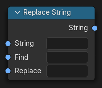
- replace(find='', replace='')#
The Replace String node replaces a string segment with another.
Path#
Utilities > Text > Replace String Node
Outputs:#
#0 string: String = ""
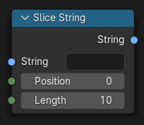
- slice(position=0, length=10)#
The Slice String node extracts a string segment from a larger string.
Path#
Utilities > Text > Slice String Node
Outputs:#
#0 string: String = ""
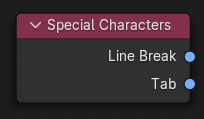
- property special_characters#
The Special Characters node is used to output string characters that can’t be typed directly with the keyboard.
Path#
Utilities > Text > Special Characters Node
Outputs:#
#0 line_break: String = ""#1 tab: String = ""
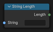
- property length#
The String Length node outputs the number of characters in the input string.
Path#
Utilities > Text > String Length Node
Outputs:#
#0 length: Integer = 0
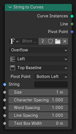
- to_curves(align_x='LEFT', align_y='TOP_BASELINE', overflow='OVERFLOW', pivot_mode='BOTTOM_LEFT', font=None, size=1.0, character_spacing=1.0, word_spacing=1.0, line_spacing=1.0, text_box_width=0.0, text_box_height=0.0)#
The String to Curves converts a string to curve instances. Each unique character used in the string is converted to a curve once, and further uses of that character are more instances of the same geometry.
Path#
Utilities > Text > String to Curves Node
Properties:#
align_x:LEFT,CENTER,RIGHT,JUSTIFY,FLUSHalign_y:TOP_BASELINE,TOP,MIDDLE,BOTTOM_BASELINE,BOTTOMoverflow:OVERFLOW,SCALE_TO_FIT,TRUNCATEpivot_mode:BOTTOM_LEFT,MIDPOINT,TOP_LEFT,TOP_CENTER,TOP_RIGHT,BOTTOM_CENTER,BOTTOM_RIGHT
Outputs:#
#0 curve_instances: Geometry = None#1 remainder: String = ""#2 line: Integer = 0#3 pivot_point: Vector = (0.0, 0.0, 0.0)
- to_curve(align_x='LEFT', align_y='TOP_BASELINE', overflow='OVERFLOW', pivot_mode='BOTTOM_LEFT', font=None, size=1.0, character_spacing=1.0, word_spacing=1.0, line_spacing=1.0, text_box_width=0.0, text_box_height=0.0)#
The String to Curves converts a string to curve instances. Each unique character used in the string is converted to a curve once, and further uses of that character are more instances of the same geometry.
Path#
Utilities > Text > String to Curves Node
Properties:#
align_x:LEFT,CENTER,RIGHT,JUSTIFY,FLUSHalign_y:TOP_BASELINE,TOP,MIDDLE,BOTTOM_BASELINE,BOTTOMoverflow:OVERFLOW,SCALE_TO_FIT,TRUNCATEpivot_mode:BOTTOM_LEFT,MIDPOINT,TOP_LEFT,TOP_CENTER,TOP_RIGHT,BOTTOM_CENTER,BOTTOM_RIGHT
Outputs:#
#0 curve_instances: Geometry = None#1 remainder: String = ""#2 line: Integer = 0#3 pivot_point: Vector = (0.0, 0.0, 0.0)
- class pynodes.datasocks.Color(bsocket: bpy.types.NodeSocket)#
Bases:
pynodes.datasocks.VectorRGBA color socket of a node, float array of 4 items in [0, inf], default (0.0, 0.0, 0.0, 0.0)
Initialization
- bl_idname = 'NodeSocketColor'#
- property red#
- property green#
- property blue#
- property alpha#
- mix(b_color=(0.5, 0.5, 0.5, 1.0), factor=0.5, blend_type='MIX', clamp_factor=True, clamp_result=False)#
The Mix Node mixes values, colors and vectors inputs using a factor to control the amount of interpolation. The Color mode has additional blending modes.
blend_type:MIX,DARKEN,MULTIPLY,BURN,LIGHTEN,SCREEN,DODGE,ADD,OVERLAY,SOFT_LIGHT,LINEAR_LIGHT,DIFFERENCE,EXCLUSION,SUBTRACT,DIVIDE,HUE,SATURATION,COLOR,VALUE
Path#
Utilities > Color > Mix Node
Outputs:#
#2 result_color: Color = (0.0, 0.0, 0.0, 0.0)
- rgb_curve(mapping=None, fac=1.0)#
The RGB Curves Node allows color corrections for each color channel and levels adjustments in the compositing context.
Path#
Utilities > Color > RGB Curves Node
Outputs:#
#0 color: Color = (0.0, 0.0, 0.0, 0.0)
- separate(mode='RGB')#
The Separate Color Node splits an image into its composite color channels. The node can output multiple Color Models depending on the Mode property.
Path#
Utilities > Color > Separate Color Node
Properties:#
mode:RGB,HSV,HSL
Outputs:#
#0 red: Float = 0.0#1 green: Float = 0.0#2 blue: Float = 0.0#3 alpha: Float = 0.0
- bright_contrast(bright=0.0, contrast=0.0)#
Path#
Color > Bright/Contrast Node
Outputs:#
#0 color: Color = (0.0, 0.0, 0.0, 0.0)
- gamma(gamma=1.0)#
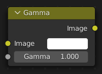
Use this node to apply a gamma correction.
Path#
Color > Gamma Node
Outputs:#
#0 color: Color = (0.0, 0.0, 0.0, 0.0)
- hue_saturation(hue=0.5, saturation=1.0, value=1.0, fac=1.0)#
The Hue Saturation Value Node applies a color transformation in the HSV Color Model.
Path#
Color > Hue Saturation Value Node
Outputs:#
#0 color: Color = (0.0, 0.0, 0.0, 0.0)
- invert(fac=1.0)#
The Invert Node inverts the colors in the input image, producing a negative.
Path#
Color > Invert Node
Outputs:#
#0 color: Color = (0.0, 0.0, 0.0, 0.0)
- normal_map(space='TANGENT', uv_map='', strength=1.0)#
The Normal Map node generates a perturbed normal from an RGB normal map image. This is usually chained with an Image Texture node in the color input, to specify the normal map image. For tangent space normal maps, the UV coordinates for the image must match, and the image texture should be set to Non-Color mode to give correct results.
Path#
Vector > Normal Map Node
Properties:#
space:TANGENT,OBJECT,WORLD,BLENDER_OBJECT,BLENDER_WORLD
Outputs:#
#0 normal: Vector = (0.0, 0.0, 0.0)
- class pynodes.datasocks.Shader(bsocket: bpy.types.NodeSocket)#
Bases:
pynodes.core.SocketShader socket of a node
Initialization
- bl_idname = 'NodeSocketShader'#
- static attribute(name='', attribute_type='GEOMETRY')#
The Attribute node allows you to retrieve attributes attached to an object or mesh.
Path#
Input > Attribute Node
Properties:#
attribute_type:GEOMETRY,OBJECT,INSTANCER,VIEW_LAYER
Outputs:#
#0 color: Color = (0.0, 0.0, 0.0, 0.0)#1 vector: Vector = (0.0, 0.0, 0.0)#2 fac: Float = 0.0#3 alpha: Float = 0.0
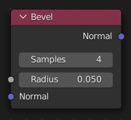
- static bevel(samples=4, radius=0.05, normal=(0.0, 0.0, 0.0))#
Cycles Only
Path#
Input > Bevel Node
Outputs:#
#0 normal: Vector = (0.0, 0.0, 0.0)
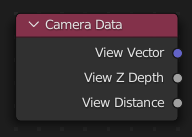
- property camera_data#
The Camera Data node returns information about the shading point relative to the camera. This could be used for example to change the shading of objects further away from the camera, or make custom fog effects.
Path#
Input > Camera Data Node
Outputs:#
#0 view_vector: Vector = (0.0, 0.0, 0.0)#1 view_z_depth: Float = 0.0#2 view_distance: Float = 0.0
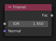
- static fresnel(ior=1.45, normal=(0.0, 0.0, 0.0))#
The Fresnel or Dielectric Fresnel node computes how much light is reflected off a layer, where the rest will be refracted through the layer. The resulting weight can be used for layering shaders with the Mix Shader node. It is dependent on the angle between the surface normal and the viewing direction.
Path#
Input > Fresnel Node
Outputs:#
#0 fac: Float = 0.0
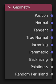
- property geometry#
The Geometry node gives geometric information about the current shading point. All vector coordinates are in World Space. For volume shaders, only the position and incoming vector are available.
Path#
Input > Geometry Node
Outputs:#
#0 position: Vector = (0.0, 0.0, 0.0)#1 normal: Vector = (0.0, 0.0, 0.0)#2 tangent: Vector = (0.0, 0.0, 0.0)#3 true_normal: Vector = (0.0, 0.0, 0.0)#4 incoming: Vector = (0.0, 0.0, 0.0)#5 parametric: Vector = (0.0, 0.0, 0.0)#6 backfacing: Float = 0.0#7 pointiness: Float = 0.0#8 random_per_island: Float = 0.0
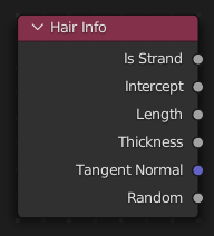
- property hair_info#
The Curves Info node gives access to Hair information.
Path#
Input > Curves Info Node
Outputs:#
#0 is_strand: Float = 0.0#1 intercept: Float = 0.0#2 length: Float = 0.0#3 thickness: Float = 0.0#4 tangent_normal: Vector = (0.0, 0.0, 0.0)#5 random: Float = 0.0
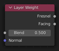
- static layer_weight(blend=0.5, normal=(0.0, 0.0, 0.0))#
The Layer Weight node outputs a weight typically used for layering shaders with the Mix Shader node.
Path#
Input > Layer Weight Node
Outputs:#
#0 fresnel: Float = 0.0#1 facing: Float = 0.0
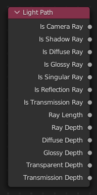
- property light_path#
The Light Path node is used to find out for which kind of incoming ray the shader is being executed; particularly useful for non-physically-based tricks. More information about the meaning of each type is in the Light Paths documentation.
Path#
Input > Light Path Node
Outputs:#
#0 is_camera_ray: Float = 0.0#1 is_shadow_ray: Float = 0.0#2 is_diffuse_ray: Float = 0.0#3 is_glossy_ray: Float = 0.0#4 is_singular_ray: Float = 0.0#5 is_reflection_ray: Float = 0.0#6 is_transmission_ray: Float = 0.0#7 ray_length: Float = 0.0#8 ray_depth: Float = 0.0#9 diffuse_depth: Float = 0.0#10 glossy_depth: Float = 0.0#11 transparent_depth: Float = 0.0#12 transmission_depth: Float = 0.0
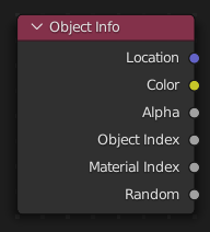
- property object_info#
The Object Info node gives information about the object instance. This can be useful to give some variation to a single material assigned to multiple instances, either manually controlled through the object index, based on the object location, or randomized for each instance. For example a Noise texture can give random colors or a Color Ramp can give a range of colors to be randomly picked from.
Path#
Input > Object Info Node
Outputs:#
#0 location: Vector = (0.0, 0.0, 0.0)#1 color: Color = (0.0, 0.0, 0.0, 0.0)#2 alpha: Float = 0.0#3 object_index: Float = 0.0#4 material_index: Float = 0.0#5 random: Float = 0.0
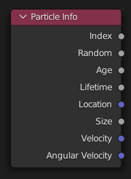
- property particle_info#
Cycles Only
Path#
Input > Particle Info Node
Outputs:#
#0 index: Float = 0.0#1 random: Float = 0.0#2 age: Float = 0.0#3 lifetime: Float = 0.0#4 location: Vector = (0.0, 0.0, 0.0)#5 size: Float = 0.0#6 velocity: Vector = (0.0, 0.0, 0.0)#7 angular_velocity: Vector = (0.0, 0.0, 0.0)
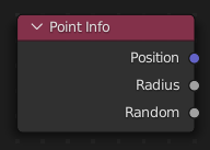
- property point_info#
Cycles Only
Path#
Input > Point Info
Outputs:#
#0 position: Vector = (0.0, 0.0, 0.0)#1 radius: Float = 0.0#2 random: Float = 0.0
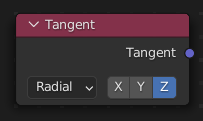
- static tangent_radial(axis='Z')#
The Tangent node generates a tangent direction for the Anisotropic BSDF.
Path#
Input > Tangent Node
Properties:#
axis:Z,X,Y
Outputs:#
#0 tangent: Vector = (0.0, 0.0, 0.0)
- static tangent_uv_map(uv_map='')#
The Tangent node generates a tangent direction for the Anisotropic BSDF.
Path#
Input > Tangent Node
Outputs:#
#0 tangent: Vector = (0.0, 0.0, 0.0)
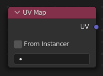
- static uv_map(from_instancer=False, uv_map='')#
The UV Map node is used to retrieve specific UV maps. Unlike the Texture Coordinate Node which only provides the active UV map, this node can retrieve any UV map belonging to the object using the material.
Path#
Input > UV Map Node
Outputs:#
#0 uv: Vector = (0.0, 0.0, 0.0)
- static color_attribute(layer_name='')#
The Color Attribute node provides access to Color Attributes as well as their alpha value.
Path#
Input > Color Attribute Node
Outputs:#
#0 color: Color = (0.0, 0.0, 0.0, 0.0)#1 alpha: Float = 0.0
- property volume_info#
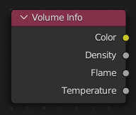
The Volume Info node provides information about Smoke Domains.
Path#
Input > Volume Info Node
Outputs:#
#0 color: Color = (0.0, 0.0, 0.0, 0.0)#1 density: Float = 0.0#2 flame: Float = 0.0#3 temperature: Float = 0.0
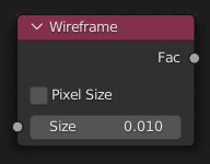
- static wire_frame(use_pixel_size=False, size=0.01)#
The Wireframe node is used to retrieve the edges of an object as it appears to Cycles. As meshes are triangulated before being processed by Cycles, topology will always appear triangulated when viewed with the Wireframe node.
Path#
Input > Wireframe Node
Outputs:#
#0 fac: Float = 0.0
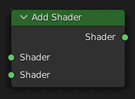
- add_shader(shader_001=None)#
The Add node is used to add two Shaders together.
Path#
Shader > Add Shader
Outputs:#
#0 shader: Shader = None
- __add__(shader_001=None)#
The Add node is used to add two Shaders together.
Path#
Shader > Add Shader
Outputs:#
#0 shader: Shader = None
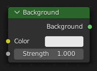
- static Background(color=(0.8, 0.8, 0.8, 1.0), strength=1.0, weight=0.0)#
The Background shader node is used to add background light emission. This node should only be used for the world surface output.
Path#
Shader > Background
Outputs:#
#0 background: Shader = None
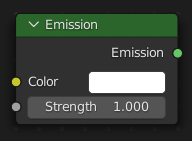
- static Emission(color=(1.0, 1.0, 1.0, 1.0), strength=1.0, weight=0.0)#
The Emission node is used to add Lambertian emission shader. This can for example, be used for material and light surface outputs.
Path#
Shader > Emission
Outputs:#
#0 emission: Shader = None
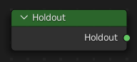
- static Holdout()#
The Holdout shader node is used to create a “hole” in the image with zero alpha transparency, which is useful for compositing (see Alpha Channel).
Path#
Shader > Holdout
Outputs:#
#0 holdout: Shader = None
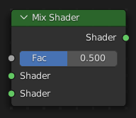
- mix(shader=None, fac=0.5)#
The Mix node is used to mix two shaders together. Mixing can be used for material layering, where the Factor input may, for example, be connected to a Blend Weight node.
Path#
Shader > Mix Shader
Outputs:#
#0 shader: Shader = None
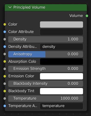
- static VolumePrincipled(color=(0.5, 0.5, 0.5, 1.0), color_attribute='', density=1.0, density_attribute='density', anisotropy=0.0, absorption_color=(0.0, 0.0, 0.0, 1.0), emission_strength=0.0, emission_color=(1.0, 1.0, 1.0, 1.0), blackbody_intensity=0.0, blackbody_tint=(1.0, 1.0, 1.0, 1.0), temperature=1000.0, temperature_attribute='temperature', weight=0.0)#
The Principled Volume shader combines all volume shading components into a single easy to use node. Volumes like smoke and fire can be rendered with a single shader node, which includes scattering, absorption and blackbody emission.
Path#
Shader > Principled Volume
Outputs:#
#0 volume: Shader = None
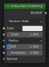
- static SubsurfaceScattering(falloff='RANDOM_WALK', color=(0.8, 0.8, 0.8, 1.0), scale=1.0, radius=(1.0, 0.2, 0.1), ior=1.4, anisotropy=0.0, normal=(0.0, 0.0, 0.0), weight=0.0)#
The Subsurface Scattering node is used to add simple subsurface multiple scattering, for materials such as skin, wax, marble, milk and others. For these materials, rather than light being reflect directly off the surface, it will penetrate the surface and bounce around internally before getting absorbed or leaving the surface at a nearby point.
Path#
Shader > Subsurface Scattering
Properties:#
falloff:RANDOM_WALK,BURLEY,RANDOM_WALK_FIXED_RADIUS
Outputs:#
#0 bssrdf: Shader = None
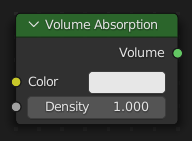
- static VolumeAbsorption(color=(0.8, 0.8, 0.8, 1.0), density=1.0, weight=0.0)#
The Volume Absorption node allows light to be absorbed as it passes through the volume. Typical usage for this node would be water and colored glass.
Path#
Shader > Volume Absorption
Outputs:#
#0 volume: Shader = None
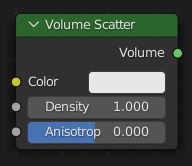
- static VolumeScatter(color=(0.8, 0.8, 0.8, 1.0), density=1.0, anisotropy=0.0, weight=0.0)#
The Volume Scatter node allows light to be scattered as it passes through the volume. Typical usage would be to add fog to a scene. It can also be used with the Volume Absorption node to create smoke.
Path#
Shader > Volume Scatter
Outputs:#
#0 volume: Shader = None
- pynodes.datasocks.access_error()#
- class pynodes.datasocks.BSDF#
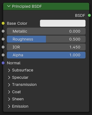
- static Principled(distribution='GGX', subsurface_method='RANDOM_WALK', base_color=(0.8, 0.8, 0.8, 1.0), subsurface=0.0, subsurface_radius=(1.0, 0.2, 0.1), subsurface_color=(0.8, 0.8, 0.8, 1.0), subsurface_ior=1.4, subsurface_anisotropy=0.0, metallic=0.0, specular=0.5, specular_tint=0.0, roughness=0.5, anisotropic=0.0, anisotropic_rotation=0.0, sheen=0.0, sheen_tint=0.5, clearcoat=0.0, clearcoat_roughness=0.03, ior=1.45, transmission=0.0, transmission_roughness=0.0, emission=(0.0, 0.0, 0.0, 1.0), emission_strength=1.0, alpha=1.0, normal=(0.0, 0.0, 0.0), clearcoat_normal=(0.0, 0.0, 0.0), tangent=(0.0, 0.0, 0.0), weight=0.0)#
The Principled BSDF that combines multiple layers into a single easy to use node. It is based on the Disney principled model also known as the “PBR” shader, making it compatible with other software such as Pixar’s Renderman® and Unreal Engine®. Image textures painted or baked from software like Substance Painter® may be directly linked to the corresponding parameters in this shader.
Path#
Shader > Principled BSDF
Properties:#
distribution:GGX,MULTI_GGXsubsurface_method:RANDOM_WALK,BURLEY,RANDOM_WALK_FIXED_RADIUS
Outputs:#
#0 bsdf: Shader = None
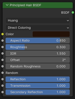
- static HairPrincipled(parametrization='COLOR', color=(0.018, 0.006, 0.002, 1.0), melanin=0.8, melanin_redness=1.0, tint=(1.0, 1.0, 1.0, 1.0), absorption_coefficient=(0.246, 0.52, 1.365), roughness=0.3, radial_roughness=0.3, coat=0.0, ior=1.55, offset=math.radians(2.0), random_color=0.0, random_roughness=0.0, random=0.0, weight=0.0)#
Cycles Only
Path#
Shader > Principled Hair BSDF
Properties:#
parametrization:COLOR,ABSORPTION,MELANIN
Outputs:#
#0 bsdf: Shader = None
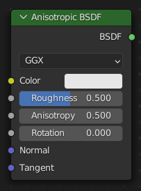
- static Anisotropic(distribution='GGX', color=(0.8, 0.8, 0.8, 1.0), roughness=0.5, anisotropy=0.5, rotation=0.0, normal=(0.0, 0.0, 0.0), tangent=(0.0, 0.0, 0.0), weight=0.0)#
Cycles Only
Path#
Shader > Anisotropic BSDF
Properties:#
distribution:GGX,BECKMANN,MULTI_GGX,ASHIKHMIN_SHIRLEY
Outputs:#
#0 bsdf: Shader = None
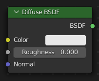
- static Diffuse(color=(0.8, 0.8, 0.8, 1.0), roughness=0.0, normal=(0.0, 0.0, 0.0), weight=0.0)#
The Diffuse BSDF node is used to add Lambertian and Oren-Nayar diffuse reflection.
Path#
Shader > Diffuse BSDF
Outputs:#
#0 bsdf: Shader = None
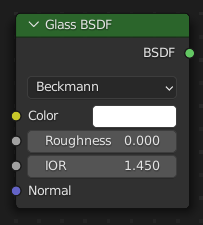
- static Glass(distribution='BECKMANN', color=(1.0, 1.0, 1.0, 1.0), roughness=0.0, ior=1.45, normal=(0.0, 0.0, 0.0), weight=0.0)#
The Glass BSDF is used to add a Glass-like shader mixing refraction and reflection at grazing angles. Like the transparent shader, only pure white will make it transparent. The glass shader tends to cause noise due to caustics. Since the Cycles path tracing integrator is not very good at rendering caustics, it helps to combine this with a transparent shader for shadows; for more details see here.
Path#
Shader > Glass BSDF
Properties:#
distribution:BECKMANN,SHARP,GGX,MULTI_GGX
Outputs:#
#0 bsdf: Shader = None
- static Glossy(distribution='GGX', color=(0.8, 0.8, 0.8, 1.0), roughness=0.5, normal=(0.0, 0.0, 0.0), weight=0.0)#
The Glossy BSDF node is used to add reflection with microfacet distribution, used for materials such as metal or mirrors.
Path#
Shader > Glossy BSDF
Properties:#
distribution:GGX,SHARP,BECKMANN,ASHIKHMIN_SHIRLEY,MULTI_GGX
Outputs:#
#0 bsdf: Shader = None

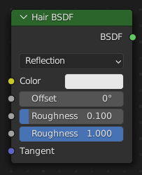
- static Hair(component='Reflection', color=(0.8, 0.8, 0.8, 1.0), offset=math.radians(0.0), roughnessu=0.1, roughnessv=1.0, tangent=(0.0, 0.0, 0.0), weight=0.0)#
Cycles Only
Path#
Shader > Hair BSDF
Properties:#
component:Reflection,Transmission
Outputs:#
#0 bsdf: Shader = None
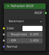
- static Refraction(distribution='BECKMANN', color=(1.0, 1.0, 1.0, 1.0), roughness=0.0, ior=1.45, normal=(0.0, 0.0, 0.0), weight=0.0)#
The Refraction BSDF is used to add glossy refraction with sharp or microfacet distribution, used for materials that transmit light. For best results this node should be considered as a building block and not be used on its own, but rather mixed with a glossy node using a Fresnel factor. Otherwise it will give quite dark results at the edges for glossy refraction.
Path#
Shader > Refraction BSDF
Properties:#
distribution:BECKMANN,SHARP,GGX
Outputs:#
#0 bsdf: Shader = None
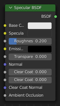
- static Specular(base_color=(0.8, 0.8, 0.8, 1.0), specular=(0.03, 0.03, 0.03, 1.0), roughness=0.2, emissive_color=(0.0, 0.0, 0.0, 1.0), transparency=0.0, normal=(0.0, 0.0, 0.0), clear_coat=0.0, clear_coat_roughness=0.0, clear_coat_normal=(0.0, 0.0, 0.0), ambient_occlusion=0.0, weight=0.0)#
Eevee Only
Path#
Shader > Specular BSDF
Outputs:#
#0 bsdf: Shader = None
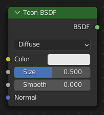
- static Toon(component='DIFFUSE', color=(0.8, 0.8, 0.8, 1.0), size=0.5, smooth=0.0, normal=(0.0, 0.0, 0.0), weight=0.0)#
Cycles Only
Path#
Shader > Toon BSDF
Properties:#
component:DIFFUSE,GLOSSY
Outputs:#
#0 bsdf: Shader = None
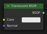
- static Translucent(color=(0.8, 0.8, 0.8, 1.0), normal=(0.0, 0.0, 0.0))#
The Translucent BSDF is used to add Lambertian diffuse transmission.
Path#
Shader > Translucent BSDF
Outputs:#
#0 bsdf: Shader = None
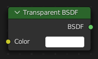
- static Transparent(color=(1.0, 1.0, 1.0, 1.0))#
The Transparent BSDF is used to add transparency without refraction, passing straight through the surface, as if there were no geometry there. Useful with alpha maps, for example. This shader affects light paths somewhat differently than other BSDFs. Note that only pure white transparent shaders are completely transparent.
Path#
Shader > Transparent BSDF
Outputs:#
#0 bsdf: Shader = None
- class pynodes.datasocks.BsdfPrincipled(distribution='GGX', subsurface_method='RANDOM_WALK', base_color=(0.8, 0.8, 0.8, 1.0), subsurface=0.0, subsurface_radius=(1.0, 0.2, 0.1), subsurface_color=(0.8, 0.8, 0.8, 1.0), subsurface_ior=1.4, subsurface_anisotropy=0.0, metallic=0.0, specular=0.5, specular_tint=0.0, roughness=0.5, anisotropic=0.0, anisotropic_rotation=0.0, sheen=0.0, sheen_tint=0.5, clearcoat=0.0, clearcoat_roughness=0.03, ior=1.45, transmission=0.0, transmission_roughness=0.0, emission=(0.0, 0.0, 0.0, 1.0), emission_strength=1.0, alpha=1.0, normal=(0.0, 0.0, 0.0), clearcoat_normal=(0.0, 0.0, 0.0), tangent=(0.0, 0.0, 0.0), weight=0.0)#
Bases:
pynodes.datasocks.Shader- property base_color#
- property subsurface#
- property subsurface_radius#
- property subsurface_color#
- property subsurface_ior#
- property subsurface_anisotropy#
- property metallic#
- property specular#
- property specular_tint#
- property roughness#
- property anisotropic#
- property anisotropic_rotation#
- property sheen#
- property sheen_tint#
- property clearcoat#
- property coat_weight#
- property clearcoat_roughness#
- property ior#
- property transmission#
- property transmission_roughness#
- property emission#
- property emission_color#
- property emission_strength#
- property alpha#
- property normal#
- property clearcoat_normal#
- property tangent#
- property weight#
- class pynodes.datasocks.Object(bsocket: bpy.types.NodeSocket)#
Bases:
pynodes.core.SocketObject socket of a node
Initialization
- bl_idname = 'NodeSocketObject'#
- property geometry#
- property relative#
- property location#
- property rotation#
- property scale#
- object_info(transform_space='ORIGINAL', as_instance=False)#
The Object Info node gets information from objects. This can be useful to control parameters in the geometry node tree with an external object, either directly by using its geometry, or via its transformation properties.
Path#
Input > Scene > Object Info Node
Properties#
transform_space:ORIGINAL,RELATIVE
Outputs:#
#0 location: Vector = (0.0, 0.0, 0.0)#1 rotation: Vector = (0.0, 0.0, 0.0)#2 scale: Vector = (0.0, 0.0, 0.0)#3 geometry: Geometry = None
- class pynodes.datasocks.Collection(bsocket: bpy.types.NodeSocket)#
Bases:
pynodes.core.SocketCollection socket of a node
Initialization
- bl_idname = 'NodeSocketCollection'#
- class pynodes.datasocks.Texture(bsocket: bpy.types.NodeSocket)#
Bases:
pynodes.core.SocketTexture socket of a node
Initialization
- bl_idname = 'NodeSocketTexture'#
- class pynodes.datasocks.Material(bsocket: bpy.types.NodeSocket)#
Bases:
pynodes.core.SocketMaterial socket of a node
Initialization
- bl_idname = 'NodeSocketMaterial'#
- material_selection()#
The Material Selection node provides a selection for meshes that use this material. Since the material_index is stored on each face, the output will be implicitly interpolated to a different domain when necessary. For example, every vertex connected to a selected face will be selected.
Path#
Material > Material Selection Node
Outputs:#
#0 selection: Boolean = False
- class pynodes.datasocks.Image(bsocket: bpy.types.NodeSocket)#
Bases:
pynodes.core.SocketImage socket of a node
Initialization
- bl_idname = 'NodeSocketImage'#
- pynodes.datasocks.InputBool(boolean=False)#
The Boolean node provides a Boolean value.
Path#
Input > Constant > Boolean Node
Outputs:#
#0 boolean: Boolean = False
- pynodes.datasocks.InputColor(color=(0.0, 0.0, 0.0, 0.0))#
Geometry Nodes Tree: The Color node outputs the color value chosen with the color picker widget.
Path#
Input > Constant > Color Node
Outputs:#
#0 color: Color = (0.0, 0.0, 0.0, 0.0)
- pynodes.datasocks.InputRGB(color=(0.5, 0.5, 0.5, 1.0))#
Shader Tree: The RGB node outputs the color value chosen with the color picker widget.
Path#
Input > RGB Node
Outputs:#
#0 color: Color = (0.5, 0.5, 0.5, 1.0)
- pynodes.datasocks.InputImage(image=None)#
The Image node provides access to a image file which allows you to conveniently enter and switch images for multiple nodes in the tree.
Path#
Input > Constant > Image Node
Outputs:#
#0 image: Image = None
- pynodes.datasocks.InputInteger(integer=0)#
The Integer node provides an integer value.
Path#
Input > Constant > Integer Node
Outputs:#
#0 integer: Integer = 0
- pynodes.datasocks.InputMaterial(material=None)#
The Material input node outputs a single material. It can be connected to other material sockets to make using the same material name in multiple places more convenient.
Path#
Input > Constant > Material Node
Outputs:#
#0 material: Material = None
- pynodes.datasocks.InputString(string='')#
The String input node creates a single string. It can be connected to attribute name sockets to make using the same attribute name in multiple places more convenient.
Path#
Input > Constant > String Node
Outputs:#
#0 string: String = ""
- pynodes.datasocks.StringToCurves(string='', align_x='LEFT', align_y='TOP_BASELINE', overflow='OVERFLOW', pivot_mode='BOTTOM_LEFT', font=None, size=1.0, character_spacing=1.0, word_spacing=1.0, line_spacing=1.0, text_box_width=0.0, text_box_height=0.0)#
The String to Curves converts a string to curve instances. Each unique character used in the string is converted to a curve once, and further uses of that character are more instances of the same geometry.
Path#
Utilities > Text > String to Curves Node
Properties:#
align_x:LEFT,CENTER,RIGHT,JUSTIFY,FLUSHalign_y:TOP_BASELINE,TOP,MIDDLE,BOTTOM_BASELINE,BOTTOMoverflow:OVERFLOW,SCALE_TO_FIT,TRUNCATEpivot_mode:BOTTOM_LEFT,MIDPOINT,TOP_LEFT,TOP_CENTER,TOP_RIGHT,BOTTOM_CENTER,BOTTOM_RIGHT
Outputs:#
#0 curve_instances: Geometry = None#1 remainder: String = ""#2 line: Integer = 0#3 pivot_point: Vector = (0.0, 0.0, 0.0)
- pynodes.datasocks.InputValue(value=0.0)#
The Value Node is a simple node to input numerical values to other nodes in the tree.
Path#
Input > Constant > Value Node
Outputs:#
#0 value: Float = 0.0
- pynodes.datasocks.InputFloat(value=0.0)#
The Value Node is a simple node to input numerical values to other nodes in the tree.
Path#
Input > Constant > Value Node
Outputs:#
#0 value: Float = 0.0
- pynodes.datasocks.InputVector(vector=(0.0, 0.0, 0.0))#
The Vector input node creates a single vector.
Path#
Input > Constant > Vector Node
Outputs:#
#0 vector: Vector = (0.0, 0.0, 0.0)
- pynodes.datasocks.CollectionInfo(collection=None, transform_space='ORIGINAL', separate_children=False, reset_children=False)#
The Collection Info node gets information from collections. This can be useful to control parameters in the geometry node tree with an external collection.
Path#
Input > Scene > Collection Info Node
Properties#
transform_space:ORIGINAL,RELATIVE
Outputs:#
#0 instances: Geometry = None
- pynodes.datasocks.ImageInfo(image=None, frame=0)#
The Image Info node gets information from image and animation. This can be useful to generate parameters in the geometry node for arbitrary images. Image information can be either general or frame-specific.
Path#
Input > Scene > Image Info Node
Outputs:#
#0 width: Integer = 0#1 height: Integer = 0#2 has_alpha: Boolean = False#3 frame_count: Integer = 0#4 fps: Float = 0.0
- pynodes.datasocks.IsViewport()#
The Is Viewport node outputs true when geometry nodes are evaluated for the viewport. For the final render the node outputs false.
Path#
Input > Scene > Is Viewport Node
Outputs:#
#0 is_viewport: Boolean = False
- pynodes.datasocks.ObjectInfo(object=None, transform_space='ORIGINAL', as_instance=False)#
The Object Info node gets information from objects. This can be useful to control parameters in the geometry node tree with an external object, either directly by using its geometry, or via its transformation properties.
Path#
Input > Scene > Object Info Node
Properties#
transform_space:ORIGINAL,RELATIVE
Outputs:#
#0 location: Vector = (0.0, 0.0, 0.0)#1 rotation: Vector = (0.0, 0.0, 0.0)#2 scale: Vector = (0.0, 0.0, 0.0)#3 geometry: Geometry = None
- pynodes.datasocks.SelfObject()#
The Self Object node outputs the object that contains the geometry nodes modifier currently being executed. This can be used to retrieve the original transforms.
Path#
Input > Scene > Self Object Node
Outputs:#
#0 self_object: Object = None
- pynodes.datasocks.GeometryNodeViewer(data_type='FLOAT', domain='AUTO', geometry=None, value=0.0, value_001=(0.0, 0.0, 0.0), value_002=(0.0, 0.0, 0.0, 0.0), value_003=0, value_004=False)#
The Viewer node allows viewing data from inside a geometry node group in the Spreadsheet Editor and the 3D Viewport.
Path#
Output > Viewer Node
Properties#
data_type:FLOAT,INT,FLOAT_VECTOR,FLOAT_COLOR,BOOLEANdomain:AUTO,POINT,EDGE,FACE,CORNER,CURVE,INSTANCE
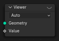
- pynodes.datasocks.ViewFloat(domain='AUTO', geometry=None, value=0.0)#
The Viewer node allows viewing data from inside a geometry node group in the Spreadsheet Editor and the 3D Viewport.
Path#
Output > Viewer Node
Properties#
domain:AUTO,POINT,EDGE,FACE,CORNER,CURVE,INSTANCE
- pynodes.datasocks.ViewVector(domain='AUTO', geometry=None, value=(0.0, 0.0, 0.0))#
The Viewer node allows viewing data from inside a geometry node group in the Spreadsheet Editor and the 3D Viewport.
Path#
Output > Viewer Node
Properties#
domain:AUTO,POINT,EDGE,FACE,CORNER,CURVE,INSTANCE
- pynodes.datasocks.ViewInteger(domain='AUTO', geometry=None, value=0)#
The Viewer node allows viewing data from inside a geometry node group in the Spreadsheet Editor and the 3D Viewport.
Path#
Output > Viewer Node
Properties#
domain:AUTO,POINT,EDGE,FACE,CORNER,CURVE,INSTANCE
- pynodes.datasocks.ViewColor(domain='AUTO', geometry=None, value=(0.0, 0.0, 0.0, 0.0))#
The Viewer node allows viewing data from inside a geometry node group in the Spreadsheet Editor and the 3D Viewport.
Path#
Output > Viewer Node
Properties#
domain:AUTO,POINT,EDGE,FACE,CORNER,CURVE,INSTANCE
- pynodes.datasocks.ViewBoolean(domain='AUTO', geometry=None, value=False)#
The Viewer node allows viewing data from inside a geometry node group in the Spreadsheet Editor and the 3D Viewport.
Path#
Output > Viewer Node
Properties#
domain:AUTO,POINT,EDGE,FACE,CORNER,CURVE,INSTANCE
- pynodes.datasocks.BrickTexture(offset=0.5, offset_frequency=2, squash=1.0, squash_frequency=2, vector: pynodes.datasocks.Vector = None, color1=(0.8, 0.8, 0.8, 1.0), color2=(0.2, 0.2, 0.2, 1.0), mortar=(0.0, 0.0, 0.0, 1.0), scale=5.0, mortar_size=0.02, mortar_smooth=0.1, bias=0.0, brick_width=0.5, row_height=0.25)#
The Brick Texture is used to add a procedural texture producing bricks.
Path#
Texture > Brick Texture Node
Outputs:#
#0 color: Color = (0.0, 0.0, 0.0, 0.0)#1 fac: Float = 0.0
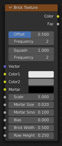
- pynodes.datasocks.CheckerTexture(vector: pynodes.datasocks.Vector = None, color1=(0.8, 0.8, 0.8, 1.0), color2=(0.2, 0.2, 0.2, 1.0), scale=5.0)#
The Checker Texture is used to add a checkerboard texture.
Path#
Texture > Checker Texture Node
Outputs:#
#0 color: Color = (0.0, 0.0, 0.0, 0.0)#1 fac: Float = 0.0
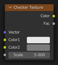
- pynodes.datasocks.GradientTexture(gradient_type='LINEAR', vector: pynodes.datasocks.Vector = None)#
The Gradient Texture node generates interpolated color and intensity values based on the input vector.
Path#
Texture > Gradient Texture Node
Properties:#
gradient_type:LINEAR,QUADRATIC,EASING,DIAGONAL,SPHERICAL,QUADRATIC_SPHERE,RADIAL
Outputs:#
#0 color: Color = (0.0, 0.0, 0.0, 0.0)#1 fac: Float = 0.0
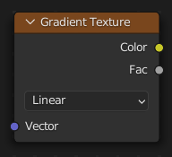
- pynodes.datasocks.ImageTextureGeo(extension='REPEAT', interpolation='Linear', image=None, vector: pynodes.datasocks.Vector = None, frame=0)#
The Image Texture node is used to add an image file as a texture. The image data is sampled with the input Vector and outputs a Color and Alpha value.
Path#
Texture > Image Texture Node
Properties:#
extension:REPEAT,EXTEND,CLIP,MIRRORinterpolation:Linear,Closest,Cubic
Outputs:#
#0 color: Color = (0.0, 0.0, 0.0, 0.0)#1 alpha: Float = 0.0
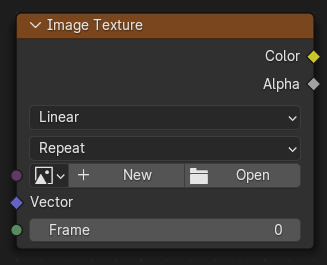
- pynodes.datasocks.MagicTexture(turbulence_depth=2, vector: pynodes.datasocks.Vector = None, scale=5.0, distortion=1.0)#
The Magic Texture node is used to add a psychedelic color texture.
Path#
Texture > Magic Texture Node
Outputs:#
#0 color: Color = (0.0, 0.0, 0.0, 0.0)#1 fac: Float = 0.0
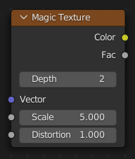
- pynodes.datasocks.MusgraveTexture(musgrave_dimensions='3D', musgrave_type='FBM', vector: pynodes.datasocks.Vector = None, w=0.0, scale=5.0, detail=2.0, dimension=2.0, lacunarity=2.0, offset=0.0, gain=1.0)#
The Musgrave Texture node evaluates a fractal Perlin noise at the input texture coordinates. Unlike the Noise Texture, which is also a fractal Perlin noise, the Musgrave Texture allows greater control over how octaves are combined.
Path#
Texture > Musgrave Texture Node
Properties:#
musgrave_dimensions:3D,1D,2D,4Dmusgrave_type:FBM,MULTIFRACTAL,RIDGED_MULTIFRACTAL,HYBRID_MULTIFRACTAL,HETERO_TERRAIN
Outputs:#
#0 fac: Float = 0.0
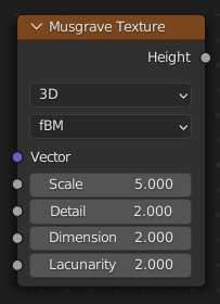
- pynodes.datasocks.NoiseTexture(noise_dimensions='3D', vector: pynodes.datasocks.Vector = None, w=0.0, scale=5.0, detail=2.0, roughness=0.5, lacunarity=2.0, distortion=0.0)#
The Noise Texture node evaluates a fractal Perlin noise at the input texture coordinates.
Path#
Texture > Noise Texture Node
Properties:#
noise_dimensions:3D,1D,2D,4D
Outputs:#
#0 fac: Float = 0.0#1 color: Color = (0.0, 0.0, 0.0, 0.0)
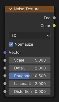
- pynodes.datasocks.VoronoiTexture(voronoi_dimensions='3D', feature='F1', distance='EUCLIDEAN', vector: pynodes.datasocks.Vector = None, w=0.0, scale=5.0, smoothness=1.0, exponent=0.5, randomness=1.0)#
The Voronoi Texture node evaluates a Worley Noise at the input texture coordinates.
Path#
Texture > Voronoi Texture Node
Properties:#
voronoi_dimensions:3D,1D,2D,4Dfeature:F1,F2,SMOOTH_F1,DISTANCE_TO_EDGE,N_SPHERE_RADIUSdistance:EUCLIDEAN,MANHATTAN,CHEBYCHEV,MINKOWSKI
Outputs:#
#0 distance: Float = 0.0#1 color: Color = (0.0, 0.0, 0.0, 0.0)#2 position: Vector = (0.0, 0.0, 0.0)#3 w: Float = 0.0#4 radius: Float = 0.0
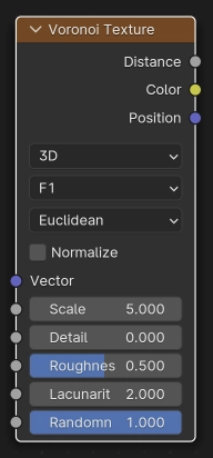
- pynodes.datasocks.WaveTexture(wave_type='BANDS', bands_direction='X', rings_direction='X', wave_profile='SIN', vector: pynodes.datasocks.Vector = None, scale=5.0, distortion=0.0, detail=2.0, detail_scale=1.0, detail_roughness=0.5, phase_offset=0.0)#
The Wave Texture node adds procedural bands or rings with noise distortion.
Path#
Texture > Wave Texture Node
Properties:#
bands_direction:X,Y,Z,DIAGONALrings_direction:X,Y,Z,SPHERICALwave_profile:SIN,SAW,TRIwave_type:BANDS,RINGS
Outputs:#
#0 color: Color = (0.0, 0.0, 0.0, 0.0)#1 fac: Float = 0.0
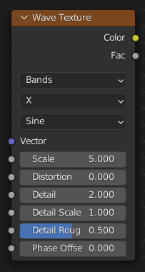
- pynodes.datasocks.WaveTextureBands(bands_direction='X', wave_profile='SIN', vector: pynodes.datasocks.Vector = None, scale=5.0, distortion=0.0, detail=2.0, detail_scale=1.0, detail_roughness=0.5, phase_offset=0.0)#
The Wave Texture node adds procedural bands or rings with noise distortion.
Path#
Texture > Wave Texture Node
Properties:#
bands_direction:X,Y,Z,DIAGONALwave_profile:SIN,SAW,TRI
Outputs:#
#0 color: Color = (0.0, 0.0, 0.0, 0.0)#1 fac: Float = 0.0
- pynodes.datasocks.WaveTextureRings(rings_direction='X', wave_profile='SIN', vector: pynodes.datasocks.Vector = None, scale=5.0, distortion=0.0, detail=2.0, detail_scale=1.0, detail_roughness=0.5, phase_offset=0.0)#
The Wave Texture node adds procedural bands or rings with noise distortion.
Path#
Texture > Wave Texture Node
Properties:#
rings_direction:X,Y,Z,SPHERICALwave_profile:SIN,SAW,TRI
Outputs:#
#0 color: Color = (0.0, 0.0, 0.0, 0.0)#1 fac: Float = 0.0
- pynodes.datasocks.WhiteNoiseTexture(noise_dimensions='3D', vector: pynodes.datasocks.Vector = None, w=0.0)#
The White Noise Texture node returns a random number based on an input Seed. The seed can be a number, a 2D vector, a 3D vector, or a 4D vector; depending on the Dimensions property. The output number ranges between zero and one.
Path#
Texture > White Noise Texture Node
Properties:#
noise_dimensions:3D,1D,2D,4D
Outputs:#
#0 value: Float = 0.0#1 color: Color = (0.0, 0.0, 0.0, 0.0)
- pynodes.datasocks.ColorRamp(fac=0.5)#
The Color Ramp Node is used for mapping values to colors with the use of a gradient.
Path#
Utilities > Color > Color Ramp Node
Outputs:#
#0 color: Color = (0.0, 0.0, 0.0, 0.0)#1 alpha: Float = 0.0
- pynodes.datasocks.CombineColor(red=0.0, green=0.0, blue=0.0, alpha=1.0, mode='RGB')#
The Combine Color Node combines an image from its composite color channels. The node can combine multiple Color Models depending on the Mode property.
Path#
Utilities > Color > Combine Color Node
Properties:#
mode:RGB,HSV,HSL
Outputs:#
#0 color: Color = (0.0, 0.0, 0.0, 0.0)
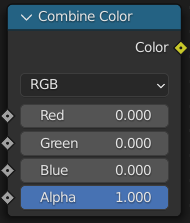
- pynodes.datasocks.CombineRGB(red=0.0, green=0.0, blue=0.0, alpha=1.0)#
The Combine Color Node combines an image from its composite color channels. The node can combine multiple Color Models depending on the Mode property.
Path#
Utilities > Color > Combine Color Node
Properties:#
mode:RGB,HSV,HSL
Outputs:#
#0 color: Color = (0.0, 0.0, 0.0, 0.0)
- pynodes.datasocks.CombineHSV(hue=0.0, saturation=0.0, value=0.0, alpha=1.0)#
The Combine Color Node combines an image from its composite color channels. The node can combine multiple Color Models depending on the Mode property.
Path#
Utilities > Color > Combine Color Node
Properties:#
mode:RGB,HSV,HSL
Outputs:#
#0 color: Color = (0.0, 0.0, 0.0, 0.0)
- pynodes.datasocks.MixFloat(factor_float=0.5, a_float=0.0, b_float=0.0, clamp_factor=True)#
The Mix Node mixes values, colors and vectors inputs using a factor to control the amount of interpolation. The Color mode has additional blending modes.
Path#
Utilities > Math > Mix Node
Outputs:#
#0 result_float: Float = 0.0
- pynodes.datasocks.MixVector(a_vector=(0.0, 0.0, 0.0), b_vector=(0.0, 0.0, 0.0), factor_float=0.5, factor_vector=(0.5, 0.5, 0.5), factor_mode='UNIFORM', clamp_factor=True)#
The Mix Node mixes images by working on the individual and corresponding pixels of the two input images. Called “Mix Color” in the shader, geometry, and texture context.
Path#
Utilities > Vector > Mix Node
Outputs:#
#1 result_vector: Vector = (0.0, 0.0, 0.0)
- pynodes.datasocks.MixColor(a_color=(0.5, 0.5, 0.5, 1.0), b_color=(0.5, 0.5, 0.5, 1.0), factor=0.5, blend_type='MIX', clamp_factor=True, clamp_result=False)#
The Mix Node mixes images by working on the individual and corresponding pixels of the two input images. Called “Mix Color” in the shader, geometry, and texture context.
Path#
Utilities > Color > Mix Node
Properties:#
blend_type: ‘MIX’, ‘DARKEN’, ‘MULTIPLY’, ‘BURN’, ‘LIGHTEN’, ‘SCREEN’, ‘DODGE’, ‘ADD’, ‘OVERLAY’, ‘SOFT_LIGHT’, ‘LINEAR_LIGHT’, ‘DIFFERENCE’, ‘EXCLUSION’, ‘SUBTRACT’, ‘DIVIDE’, ‘HUE’, ‘SATURATION’, ‘COLOR’, ‘VALUE’
Outputs:#
#2 result_color: Color = (0.0, 0.0, 0.0, 0.0)
- pynodes.datasocks.ShaderNodeRGBCurve(mapping=None, fac=1.0, color=(1.0, 1.0, 1.0, 1.0))#
The RGB Curves Node allows color corrections for each color channel and levels adjustments in the compositing context.
Path#
Utilities > Color > RGB Curves Node
Outputs:#
#0 color: Color = (0.0, 0.0, 0.0, 0.0)
- pynodes.datasocks.SeparateColor(color=(1.0, 1.0, 1.0, 1.0), mode='RGB')#
The Separate Color Node splits an image into its composite color channels. The node can output multiple Color Models depending on the Mode property.
Path#
Utilities > Color > Separate Color Node
Properties:#
mode:RGB,HSV,HSL
Outputs:#
#0 red: Float = 0.0#1 green: Float = 0.0#2 blue: Float = 0.0#3 alpha: Float = 0.0
- pynodes.datasocks.CombineXYZ(x=0.0, y=0.0, z=0.0)#
The Combine XYZ Node combines a vector from its individual components.
Path#
Utilities > Vector > Combine XYZ Node
Outputs:#
#0 vector: Vector = (0.0, 0.0, 0.0)
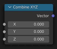
- pynodes.datasocks.FloatMath(operation='ADD', use_clamp=False, value=0.5, value_001=0.5, value_002=0.5)#
The Math Node performs math operations.
Path#
Utilities > Math > Math Node
Properties:#
operation:ADD,SUBTRACT,MULTIPLY,DIVIDE,MULTIPLY_ADD,POWER,LOGARITHM,SQRT,INVERSE_SQRT,ABSOLUTE,EXPONENT,MINIMUM,MAXIMUM,LESS_THAN,GREATER_THAN,SIGN,COMPARE,SMOOTH_MIN,SMOOTH_MAX,ROUND,FLOOR,CEIL,TRUNC,FRACT,MODULO,WRAP,SNAP,PINGPONG,SINE,COSINE,TANGENT,ARCSINE,ARCCOSINE,ARCTANGENT,ARCTAN2,SINH,COSH,TANH,RADIANS,DEGREES
Outputs:#
#0 value: Float = 0.0
- pynodes.datasocks.VectorMath(operation='ADD', vector=(0.0, 0.0, 0.0), vector_001=(0.0, 0.0, 0.0), vector_002=(0.0, 0.0, 0.0), scale=1.0)#
The Vector Math node performs the selected math operation on the input vectors.
Path#
Utilities > Vector > Vector Math Node
Properties:#
operation:ADD,SUBTRACT,MULTIPLY,DIVIDE,MULTIPLY_ADD,CROSS_PRODUCT,PROJECT,REFLECT,REFRACT,FACEFORWARD,DOT_PRODUCT,DISTANCE,LENGTH,SCALE,NORMALIZE,ABSOLUTE,MINIMUM,MAXIMUM,FLOOR,CEIL,FRACTION,MODULO,WRAP,SNAP,SINE,COSINE,TANGENT
Outputs:#
#0 vector: Vector = (0.0, 0.0, 0.0)#1 value: Float = 0.0
- pynodes.datasocks.BooleanMath(operation='AND', boolean=False, boolean_001=False)#
The Boolean Math node performs a basic logical operation on its inputs.
Path#
Utilities > Math > Boolean Math Node
Properties:#
operation:AND,OR,NOT,NAND,NOR,XNOR,XOR,IMPLY,NIMPLY
Outputs:#
#0 boolean: Boolean = False
- pynodes.datasocks.Compare(data_type='FLOAT', mode='ELEMENT', operation='GREATER_THAN', a=0.0, b=0.0, a_int=0, b_int=0, a_vec3=(0.0, 0.0, 0.0), b_vec3=(0.0, 0.0, 0.0), a_col=(0.0, 0.0, 0.0, 0.0), b_col=(0.0, 0.0, 0.0, 0.0), a_str='', b_str='', c=0.9, angle=math.radians(5.0), epsilon=0.001)#
The Compare node takes two inputs and does an operation to determine whether they are similar. The node can work on all generic data types, and has modes for vectors that contain more complex comparisons, which can help to reduce the number of necessary nodes, and make a node tree more readable.
Path#
Utilities > Math > Compare Node
Properties:#
data_type:FLOAT,INT,VECTOR,STRING,RGBAmode:ELEMENT,LENGTH,AVERAGE,DOT_PRODUCT,DIRECTIONoperation:GREATER_THAN,LESS_THAN,LESS_EQUAL,GREATER_EQUAL,EQUAL,NOT_EQUAL
Outputs:#
#0 result: Boolean = False
- pynodes.datasocks.Switch(input_type='GEOMETRY', switch=False, switch_001=False, false=0.0, true=0.0, false_001=0, true_001=0, false_002=False, true_002=True, false_003=(0.0, 0.0, 0.0), true_003=(0.0, 0.0, 0.0), false_004=(0.8, 0.8, 0.8, 1.0), true_004=(0.8, 0.8, 0.8, 1.0), false_005='', true_005='', false_006=None, true_006=None, false_007=None, true_007=None, false_008=None, true_008=None, false_009=None, true_009=None, false_010=None, true_010=None, false_011=None, true_011=None)#
The Switch node outputs one of two inputs depending on a condition. Only the input that is passed through the node is computed.
Path#
Utilities > Switch Node
Properties:#
input_type:GEOMETRY,FLOAT,INT,BOOLEAN,VECTOR,STRING,RGBA,OBJECT,IMAGE,COLLECTION,TEXTURE,MATERIAL
Outputs:#
#0 output: Float = 0.0#1 output_001: Integer = 0#2 output_002: Boolean = False#3 output_003: Vector = (0.0, 0.0, 0.0)#4 output_004: Color = (0.0, 0.0, 0.0, 0.0)#5 output_005: String = ""#6 output_006: Geometry = None#7 output_007: Object = None#8 output_008: Collection = None#9 output_009: Texture = None#10 output_010: Material = None#11 output_011: Image = None
- pynodes.datasocks.RandomFloat(min=0.0, max=1.0, id=None, seed=0)#
The Random Value node outputs a white noise like value as a Float, Integer, Vector, or Boolean field.
Path#
Utilities > Random Value Node
Outputs:#
#1 value_001: Float = 0.0
- pynodes.datasocks.RandomInteger(min=0, max=100, id: pynodes.datasocks.Integer = None, seed=0)#
The Random Value node outputs a white noise like value as a Float, Integer, Vector, or Boolean field.
Path#
Utilities > Random Value Node
Outputs:#
#2 value_002: Integer = 0
- pynodes.datasocks.RandomVector(min=(0.0, 0.0, 0.0), max=(1.0, 1.0, 1.0), id=None, seed=0)#
The Random Value node outputs a white noise like value as a Float, Integer, Vector, or Boolean field.
Path#
Utilities > Random Value Node
Outputs:#
#0 value: Vector = (0.0, 0.0, 0.0)
- pynodes.datasocks.RandomBoolean(probability=0.5, id=None, seed=0)#
The Random Value node outputs a white noise like value as a Float, Integer, Vector, or Boolean field.
Path#
Utilities > Random Value Node
Outputs:#
#3 value_003: Boolean = False
- pynodes.datasocks.InputPosition()#
The Position node outputs a vector of each point of the geometry the node is connected to.
Path#
Geometry > Read > Position Node
Outputs:#
#0 position: Vector = (0.0, 0.0, 0.0)
- pynodes.datasocks.InputIndex()#
The Index node gives an integer value indicating the position of each element in the list, starting at zero. This depends on the internal order of the data in the geometry, which is not necessarily visible in the 3D Viewport. However, the index value is visible in the left-most column in the Spreadsheet Editor.
Path#
Geometry > Read > Index Node
Outputs:#
#0 index: Integer = 0
- pynodes.datasocks.SceneTime()#
The Scene Time node outputs the current time in the scene’s animation in units of seconds or frames.
Path#
Input > Scene > Scene Time Node
Outputs:#
#0 seconds: Float = 0.0#1 frame: Float = 0.0
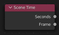
- pynodes.datasocks.AmbientOcclusion(inside=False, only_local=False, samples=16, color=(1.0, 1.0, 1.0, 1.0), distance=1.0, normal=(0.0, 0.0, 0.0))#
The Ambient Occlusion shader computes how much the hemisphere above the shading point is occluded. This can be used for procedural texturing, for example to add weathering effects to corners only.
Path#
Input > Ambient Occlusion
Outputs:#
#0 color: Color = (0.0, 0.0, 0.0, 0.0)#1 ao: Float = 0.0
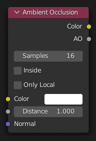
- pynodes.datasocks.EnvironmentTexture(image=None, interpolation='Linear', projection='EQUIRECTANGULAR', vector=(0.0, 0.0, 0.0))#
The Node Environmental Texture is used to light your scene using an environment map image file as a texture.
Path#
Texture > Environment Texture Node
Properties:#
interpolation:Linear,Closest,Cubic,Smartprojection:EQUIRECTANGULAR,MIRROR_BALL
Outputs:#
#0 color: Color = (0.0, 0.0, 0.0, 0.0)

- pynodes.datasocks.IES_Texture(mode='INTERNAL', filepath='', ies=None, vector=(0.0, 0.0, 0.0), strength=1.0)#
The IES Texture is used to match real world lights based on IES files (IES). IES files store the directional intensity distribution of light sources.
Path#
Texture > IES Texture Node
Properties:#
mode:INTERNAL,EXTERNAL
Outputs:#
#0 fac: Float = 0.0
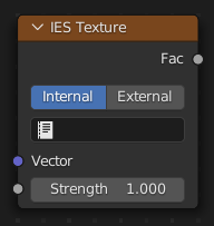
- pynodes.datasocks.ImageTexture(image=None, interpolation='Linear', projection='FLAT', extension='REPEAT', image_user=None, projection_blend=0.0, vector=(0.0, 0.0, 0.0))#
The Image Texture is used to add an image file as a texture.
Path#
Texture > Image Texture Node
Properties:#
extension:REPEAT,EXTEND,CLIP,MIRRORinterpolation:Linear,Closest,Cubic,Smartprojection:FLAT,BOX,SPHERE,TUBE
Outputs:#
#0 color: Color = (0.0, 0.0, 0.0, 0.0)#1 alpha: Float = 0.0
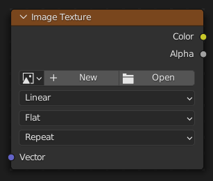
- pynodes.datasocks.PointDensity(interpolation='Linear', particle_color_source='PARTICLE_AGE', point_source='PARTICLE_SYSTEM', space='OBJECT', vertex_color_source='VERTEX_COLOR', object=None, particle_system=None, radius=0.3, resolution=100, vertex_attribute_name='', vector=(0.0, 0.0, 0.0))#
The Point Density node is used to add volumetric points for each particle or vertex of another object.
Path#
Texture > Point Density Node
Properties:#
interpolation:Linear,Closest,Cubicparticle_color_source:PARTICLE_AGE,PARTICLE_SPEED,PARTICLE_VELOCITYpoint_source:PARTICLE_SYSTEM,OBJECTspace:OBJECT,WORLDvertex_color_source:VERTEX_COLOR,VERTEX_WEIGHT,VERTEX_NORMAL
Outputs:#
#0 color: Color = (0.0, 0.0, 0.0, 0.0)#1 density: Float = 0.0
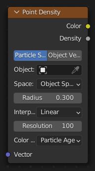
- pynodes.datasocks.SkyTexture(sky_type='NISHITA', air_density=1.0, altitude=0.0, dust_density=1.0, ground_albedo=0.3, ozone_density=1.0, sun_direction=(0.0, 0.0, 1.0), sun_disc=True, sun_elevation=math.radians(15.0), sun_intensity=1.0, sun_rotation=0.0, sun_size=math.radians(0.545), turbidity=2.2, vector=(0.0, 0.0, 0.0))#
The Sky Texture node adds a procedural Sky texture.
Path#
Texture > Sky Texture Node
Properties:#
sky_type:NISHITA,PREETHAM,HOSEK_WILKIE
Outputs:#
#0 color: Color = (0.0, 0.0, 0.0, 0.0)
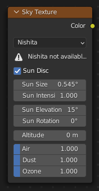
- pynodes.datasocks.BrightContrast(color=(1.0, 1.0, 1.0, 1.0), bright=0.0, contrast=0.0)#
ShaderNodeBrightContrast
Path#
Color > Bright/Contrast Node
Outputs:#
#0 color: Color = (0.0, 0.0, 0.0, 0.0)
- pynodes.datasocks.ColorGamma(color=(1.0, 1.0, 1.0, 1.0), gamma=1.0)#
Use this node to apply a gamma correction.
Path#
Color > Gamma Node
Outputs:#
#0 color: Color = (0.0, 0.0, 0.0, 0.0)
- pynodes.datasocks.HueSaturation(hue=0.5, saturation=1.0, value=1.0, fac=1.0, color=(0.8, 0.8, 0.8, 1.0))#
The Hue Saturation Value Node applies a color transformation in the HSV Color Model.
Path#
Color > Hue Saturation Value Node
Outputs:#
#0 color: Color = (0.0, 0.0, 0.0, 0.0)
- pynodes.datasocks.LightFalloff(strength=100.0, smooth=0.0)#
Cycles Only
Path#
Color > Light Falloff Node
Outputs:#
#0 quadratic: Float = 0.0#1 linear: Float = 0.0#2 constant: Float = 0.0
- pynodes.datasocks.ShaderNodeBump(invert=False, strength=1.0, distance=1.0, height=1.0, normal=(0.0, 0.0, 0.0))#
The Bump node generates a perturbed normal from a height texture, for bump mapping. The height value will be sampled at the shading point and two nearby points on the surface to determine the local direction of the normal.
Path#
Vector > Bump Node
Outputs:#
#0 normal: Vector = (0.0, 0.0, 0.0)
- pynodes.datasocks.ShaderNodeDisplacement(space='OBJECT', height=0.0, midlevel=0.5, scale=1.0, normal=(0.0, 0.0, 0.0))#
The Displacement node is used to displace the surface along the surface normal, to add more detail to the geometry. Both procedural textures and baked displacement maps can be used.
Path#
Vector > Displacement Node
Properties:#
space:OBJECT,WORLD
Outputs:#
#0 displacement: Vector = (0.0, 0.0, 0.0)
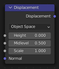
- pynodes.datasocks.ShaderNodeNormal(normal=(0.0, 0.0, 1.0))#
The Normal node generates a normal vector and a dot product.
Path#
Vector > Normal Node
Outputs:#
#0 normal: Vector = (0.0, 0.0, 1.0)#1 dot: Float = 0.0
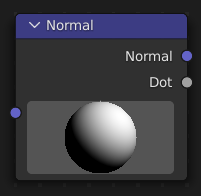
- pynodes.datasocks.ShaderNodeNormalMap(space='TANGENT', uv_map='', strength=1.0, color=(0.5, 0.5, 1.0, 1.0))#
The Normal Map node generates a perturbed normal from an RGB normal map image. This is usually chained with an Image Texture node in the color input, to specify the normal map image. For tangent space normal maps, the UV coordinates for the image must match, and the image texture should be set to Non-Color mode to give correct results.
Path#
Vector > Normal Map Node
Properties:#
space:TANGENT,OBJECT,WORLD,BLENDER_OBJECT,BLENDER_WORLD
Outputs:#
#0 normal: Vector = (0.0, 0.0, 0.0)
- pynodes.datasocks.ShaderNodeVectorDisplacement(space='TANGENT', vector=(0.0, 0.0, 0.0, 0.0), midlevel=0.0, scale=1.0)#
The Vector Displacement node is used to displace the surface along arbitrary directions, unlike the regular Displacement node which only displaces along the surface normal.
Path#
Vector > Vector Displacement Node
Properties:#
space:TANGENT,OBJECT,WORLD
Outputs:#
#0 displacement: Vector = (0.0, 0.0, 0.0)
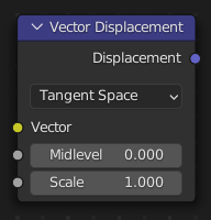
- pynodes.datasocks.ShaderNodeVectorTransform(convert_from='WORLD', convert_to='OBJECT', vector_type='VECTOR', vector=(0.5, 0.5, 0.5))#
The Vector Transform node allows converting a vector, point, or normal between world and camera and object coordinate space.
Path#
Vector > Vector Transform Node
Properties:#
convert_from:WORLD,OBJECT,CAMERAconvert_to:OBJECT,WORLD,CAMERAvector_type:VECTOR,POINT,NORMAL
Outputs:#
#0 vector: Vector = (0.0, 0.0, 0.0)
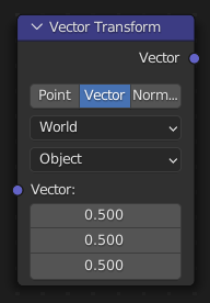
- pynodes.datasocks.Blackbody(temperature=1500.0)#
The Blackbody node converts a blackbody temperature to RGB value. This can be useful for materials that emit light at natural occurring frequencies.
Path#
Converter > Blackbody Node
Outputs:#
#0 color: Color = (0.0, 0.0, 0.0, 0.0)
- pynodes.datasocks.ShaderNodeCombineColor(red=0.0, green=0.0, blue=0.0, mode='RGB')#
The Combine Color Node combines an image from its composite color channels. The node can combine multiple Color Models depending on the Mode property.
Path#
Converter > Combine Color Node
Properties:#
mode:RGB,HSV,HSL
Outputs:#
#0 color: Color = (0.0, 0.0, 0.0, 0.0)
- pynodes.datasocks.ShaderNodeRGBToBW(color=(0.5, 0.5, 0.5, 1.0))#
The RGB to BW Node maps an RGB color image to a gray-scale by the luminance.
Path#
Converter > RGB to BW Node
Outputs:#
#0 val: Float = 0.0
- pynodes.datasocks.ShaderNodeSeparateColor(color=(0.8, 0.8, 0.8, 1.0), mode='RGB')#
The Separate Color Node splits an image into its composite color channels. The node can output multiple Color Models depending on the Mode property.
Path#
Converter > Separate Color Node
Properties:#
mode:RGB,HSV,HSL
Outputs:#
#0 red: Float = 0.0#1 green: Float = 0.0#2 blue: Float = 0.0
- pynodes.datasocks.ShaderNodeWavelength(wavelength=500.0)#
The Wavelength node converts a wavelength value to an RGB value. This can be used to achieve a specific color on the light spectrum.
Path#
Converter > Wavelength Node
Outputs:#
#0 color: Color = (0.0, 0.0, 0.0, 0.0)
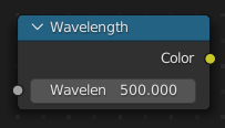
- pynodes.datasocks.TextureCoord(object=None, from_instancer=False)#
The Texture Coordinate node is commonly used for the coordinates of textures, typically used as inputs for the Vector input for texture nodes.
Path#
Input > Texture Coordinate Node
Outputs:#
#0 generated: Vector = (0.0, 0.0, 0.0)#1 normal: Vector = (0.0, 0.0, 0.0)#2 uv: Vector = (0.0, 0.0, 0.0)#3 object: Vector = (0.0, 0.0, 0.0)#4 camera: Vector = (0.0, 0.0, 0.0)#5 window: Vector = (0.0, 0.0, 0.0)#6 reflection: Vector = (0.0, 0.0, 0.0)
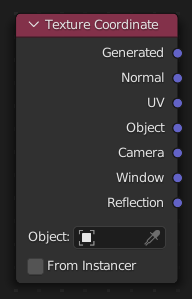
- pynodes.datasocks.ShaderNodeMapping(vector_type='POINT', vector=(0.0, 0.0, 0.0), location=(0.0, 0.0, 0.0), rotation=(0.0, 0.0, 0.0), scale=(1.0, 1.0, 1.0))#
The Mapping node transforms the input vector by applying translation, rotation, and scaling.
Path#
Vector > Mapping Node
Properties:#
vector_type:POINT,TEXTURE,VECTOR,NORMAL
Outputs:#
#0 vector: Vector = (0.0, 0.0, 0.0)
- pynodes.datasocks.ShaderGeometry()#
The Geometry node gives geometric information about the current shading point. All vector coordinates are in World Space. For volume shaders, only the position and incoming vector are available.
Path#
Input > Geometry Node
Outputs:#
#0 position: Vector = (0.0, 0.0, 0.0)#1 normal: Vector = (0.0, 0.0, 0.0)#2 tangent: Vector = (0.0, 0.0, 0.0)#3 true_normal: Vector = (0.0, 0.0, 0.0)#4 incoming: Vector = (0.0, 0.0, 0.0)#5 parametric: Vector = (0.0, 0.0, 0.0)#6 backfacing: Float = 0.0#7 pointiness: Float = 0.0#8 random_per_island: Float = 0.0
- pynodes.datasocks.MixShader(shader1=None, shader2=None, fac=0.5)#
The Mix node is used to mix two shaders together. Mixing can be used for material layering, where the Factor input may, for example, be connected to a Blend Weight node.
Path#
Shader > Mix Shader
Outputs:#
#0 shader: Shader = None
- pynodes.datasocks.ShaderScript(mode='INTERNAL', script: bpy.types.Text = None, **kwargs)#
It is also possible to create your own nodes using Open Shading Language (OSL). These nodes will only work with the CPU and OptiX rendering backend. OSL was designed for node-based shading, and each OSL shader corresponds to one node in a node setup. To add an OSL shader, add a script node and link it to a text data-block or an external file. Input and output sockets will be created from the shader parameters on clicking the update button in the Node or the Text editor. OSL shaders can be linked to the node in a few different ways. With the Internal mode, a text data-block is used to store the OSL shader, and the OSO bytecode is stored in the node itself. This is useful for distributing a blend-file with everything packed into it. The External mode can be used to specify a
.oslfile from a drive, and this will then be automatically compiled into a.osofile in the same directory. It is also possible to specify a path to a.osofile, which will then be used directly, with compilation done manually by the user. The third option is to specify just the module name, which will be looked up in the shader search path.bpy.data.scenes["Scene"].render.engine = "CYCLES" bpy.data.scenes["Scene"].cycles.shading_system = True
Path#
Input > Geometry Node
Outputs:#
#0 position: Vector = (0.0, 0.0, 0.0)#1 normal: Vector = (0.0, 0.0, 0.0)#2 tangent: Vector = (0.0, 0.0, 0.0)#3 true_normal: Vector = (0.0, 0.0, 0.0)#4 incoming: Vector = (0.0, 0.0, 0.0)#5 parametric: Vector = (0.0, 0.0, 0.0)#6 backfacing: Float = 0.0#7 pointiness: Float = 0.0#8 random_per_island: Float = 0.0
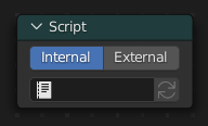
- pynodes.datasocks.join_strings(*strings: str, delimiter='')#
The Join Strings node combines any number of input strings into the output string. The order of the result depends on the vertical ordering of the inputs in the multi-input socket.
Path#
Utilities > Text > Join Strings Node
Outputs:#
#0 string: String = ""
- pynodes.datasocks.Attribute(name='', attribute_type='GEOMETRY')#
The Attribute node allows you to retrieve attributes attached to an object or mesh.
Path#
Input > Attribute Node
Properties:#
attribute_type:GEOMETRY,OBJECT,INSTANCER,VIEW_LAYER
Outputs:#
#0 color: Color = (0.0, 0.0, 0.0, 0.0)#1 vector: Vector = (0.0, 0.0, 0.0)#2 fac: Float = 0.0#3 alpha: Float = 0.0